
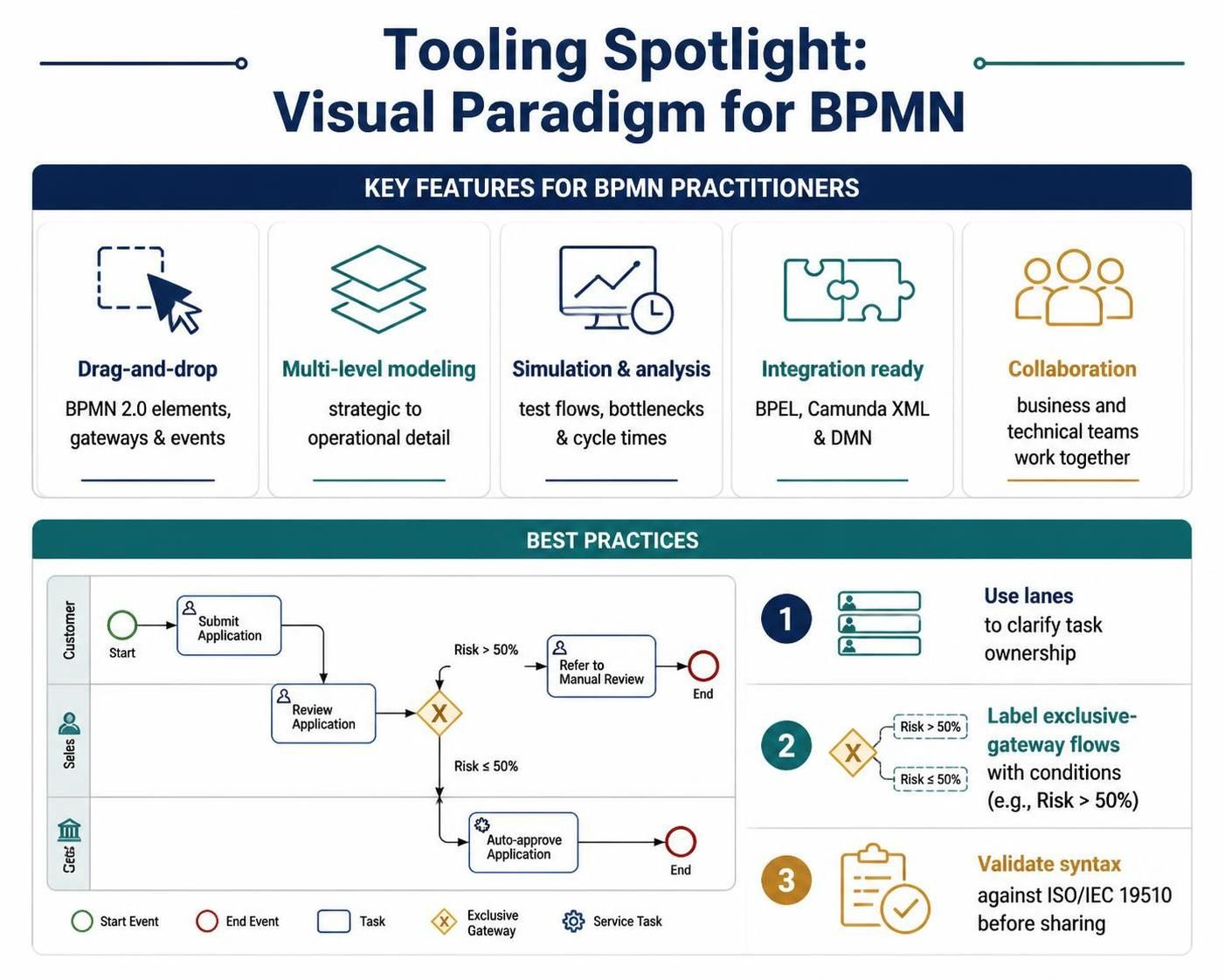
In the rapidly evolving landscape of business process management, the gap between abstract business strategy and technical implementation often leads to inefficiency. Visual Paradigm serves as a critical bridge in this context, offering an enterprise-grade environment for modeling complex workflows using the Business Process Model and Notation (BPMN) standard. This tutorial explores the architectural concepts behind BPMN modeling, focusing on how to utilize Visual Paradigm’s features to ensure clarity, precision, and operational agility.
The Architecture of BPMN Modeling
BPMN is not merely a drawing standard; it is a semantically rich language that defines the logic of business operations. At the core of any BPMN diagram are three fundamental components:
- Flow Objects: The active elements of the process, including Events (circles), Activities (rounded rectangles), and Gateways (diamonds) that control the flow of logic.
- Connecting Objects: Arrows that link flow objects, defining the sequence of operations and the direction of data flow.
- Participants: The containers for processes, typically represented as “Swimlanes” (Pools) that categorize responsibilities by role or department.
Visual Paradigm enhances this architecture by supporting a multi-level modeling approach. Practitioners can switch seamlessly between strategic diagrams for high-level overview and operational diagrams for granular detail, all while maintaining the integrity of the underlying model structure.
Implementing Best Practices: The Risk Assessment Workflow
To understand how these concepts translate into a functional process, let us analyze a standard “Application Review” workflow. This process demonstrates how to effectively assign responsibility, handle conditional logic, and ensure process validation.
1. Structuring Responsibility with Swimlanes
The foundation of a readable BPMN diagram is the clear assignment of tasks. In Visual Paradigm, the “Drag-and-Drop” interface allows users to intuitively assign tasks to specific participants. For example, in an application review process, the “Submit Application” task belongs to the Customer lane, while “Review Application” belongs to the Sales lane, and “Auto-approve” is handled by the System (represented as a Service Task).
2. Handling Logic with Exclusive Gateways
Business processes rarely follow a linear path. Conditional logic is managed using Gateways. The Exclusive Gateway (often shaped like a diamond with an ‘X’) is used when only one path can be taken based on a specific condition.
Consider the “Review Application” process. Once the application is reviewed, the system must decide whether to approve it automatically or refer it for manual review. This decision point is modeled using an Exclusive Gateway branching into two paths: Risk > 50% and Risk ≤ 50%.
Visual Paradigm supports the integration of DMN (Decision Model and Notation) editors, allowing you to define complex decision logic separately from the process flow, ensuring that the decision rules are clear and maintainable.
3. Visualizing the Logic Flow
The following pseudo-code representation illustrates the logical flow of the process described above, highlighting the decision points and lane assignments.
Start Event (Customer)
   |
   v
Task: Submit Application (Customer)
   |
   v
Task: Review Application (Sales)
   |
   v
Gateway: Exclusive (Check Risk Level)
   |
   +-- [Condition: Risk > 50%] --> Task: Refer to Manual Review (Sales) --> End Event
   |
   +-- [Condition: Risk <= 50%] --> Task: Auto-approve Application (System) --> End Event
Simulation and Analysis Capabilities
Visual Paradigm moves beyond static modeling by offering built-in simulation capabilities. Once a process is modeled, you can run simulations to test process flows, identify potential bottlenecks, and calculate cycle times before the process is ever implemented in the real world.
This feature is crucial for “Integration Ready” scenarios. By simulating the process, you can ensure that the logic holds up under various load conditions and that the handoffs between the Customer, Sales, and System lanes are efficient.
Validation and Collaboration
The final step in the modeling lifecycle is validation. Visual Paradigm includes a built-in validator that checks the diagram against ISO/IEC 19510 standards. This ensures that the diagram adheres to strict syntactic rules, preventing errors that could arise during code generation or deployment.
Furthermore, the tool’s cloud-based collaboration features enable real-time interaction between business analysts and technical teams. This ensures that the “bridge” between business intent and technical reality remains intact throughout the project lifecycle, allowing for agile responses to changing requirements.
Conclusion
By mastering the core elements of BPMN—Flow Objects, Connecting Objects, and Participants—and utilizing tools like Visual Paradigm to enforce best practices, organizations can achieve greater agility. Whether mapping a simple approval workflow or a complex, multi-party insurance claim process, the structural rigor provided by these tools turns abstract ideas into executable, efficient business processes.