
System architecture can often feel overwhelming when trying to communicate high-level concepts to stakeholders. The C4 model solves this by breaking down complex systems into manageable layers. In this tutorial, we will focus on Level 1: The System Context Diagram. This diagram serves as the “map” for your entire system, showing how your software fits into the broader world.
We will explore how to create these diagrams using code with VPasCode, a diagram-as-code tool by Visual Paradigm. By treating diagrams as code, teams can leverage version control, automated testing, and collaborative editing.
Understanding the C4 System Context Diagram
A System Context diagram provides a single, high-level view of the software system. It defines the boundaries of your application and identifies the external entities that interact with it. Unlike lower-level diagrams, this view does not show internal components (like databases or microservices) in detail; instead, it focuses on the “big picture.”
Key Components
To build a robust System Context diagram, you need to identify three specific types of elements:
- Person: A human user or actor who interacts with the system (e.g., Customers, Administrators, Managers). They are the “Who.”
- System: The primary software system being described (e.g., Internet Banking, Order Processing).
- External System (SystemExt): Third-party software or services that your system relies on or communicates with (e.g., Email Servers, Payment Gateways, Legacy Databases). These are often denoted by a grey box in C4 diagrams.
Step-by-Step: Building a Banking System Context
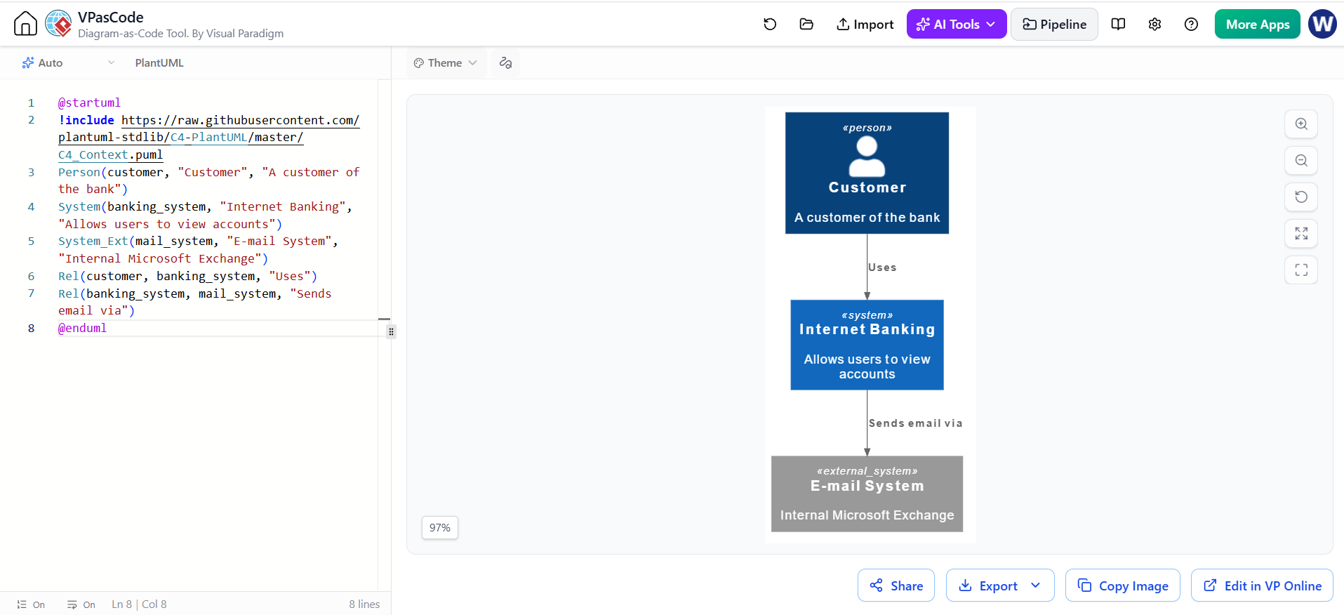
Let’s walk through creating a System Context diagram for an Internet Banking System. We will define the actors and the external dependencies using the PlantUML syntax.
1. Setup and Includes
First, we must tell the renderer which C4 library to use. This ensures our shapes render correctly according to the C4 standard. We use the !include directive to pull the library from the PlantUML standard library.
@startuml
!include https://raw.githubusercontent.com/plantuml-stdlib/C4-PlantUML/master/C4_Context.puml

title Internet Banking System Context Diagram

' Define the System
System(banking_system, "Internet Banking", "Allows users to view accounts")

' Define the Person
Person(customer, "Customer", "A customer of the bank")

' Define the External System
System_Ext(mail_system, "E-mail System", "Internal Microsoft Exchange")

' Define Relationships
Rel(customer, banking_system, "Uses")
Rel(banking_system, mail_system, "Sends email via")

@enduml
2. Defining the System and Actors
Notice the syntax used in the code above. The structure is highly readable: TYPEID, "Label", "Description".
Person(customer, "Customer", "A customer of the bank"): Defines a human actor. The IDcustomeris used to reference this element later when drawing lines.SystemExt(mailsystem, "E-mail System", ...): This is crucial. By usingSystemExtinstead ofSystem, we visually distinguish internal systems from external dependencies. In the rendered output, this appears as a grey box, signaling that the logic resides outside our control.
3. Mapping Relationships
The Rel() function draws the lines between elements. The syntax is Rel(IDA, IDB, "Relationship Label").
Rel(customer, banking_system, "Uses")
Rel(banking_system, mail_system, "Sends email via")
In the example, we see two distinct flows: the customer using the banking system, and the banking system triggering an external email system. The label “Sends email via” is vital—it adds semantic meaning that a plain arrow cannot convey.
Why Use VPasCode for C4?
While you can draw these diagrams visually in tools like Visual Paradigm, using VPasCode (the code editor interface) offers distinct advantages:
- Version Control Friendly: Diagrams are just text. You can use Git to track changes, resolve merge conflicts, and review diagram updates just like you would with code.
- Consistency: Code forces a standard structure. You cannot accidentally leave out a relationship label if you type it into the code editor.
- Speed: Once you know the syntax, typing
Rel()is often faster than dragging and dropping connectors.
Conclusion
Creating a System Context diagram is the foundational step in modern software architecture. By using PlantUML within VPasCode, you ensure your documentation is accurate, maintainable, and easily integrated into your development workflow. Start by defining your boundaries, clearly distinguishing your internal logic from external dependencies, and your architecture will be clear to all.