
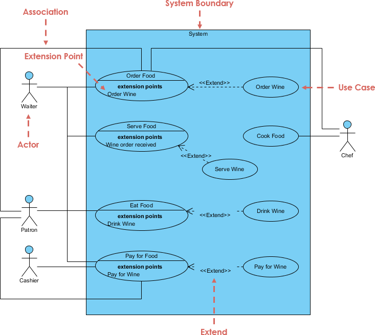
In the realm of software engineering and systems analysis, the Use Case Diagram serves as a fundamental blueprint. It bridges the gap between business requirements and technical implementation by visualizing how users interact with a system. The diagram presented here illustrates a robust Restaurant Management System, showcasing the intricate relationship between external entities (Actors) and internal processes (Use Cases) within a defined System Boundary.
1. The Foundation: System Boundary & Actors
The large blue rectangle represents the System Boundary. This conceptual wall defines what is inside the system (the functionality it provides) and what is outside (the environment). Anything inside the blue box is part of the software’s responsibility, while anything outside represents the external world.
Interacting with this system are Actors, depicted as stick figures. Actors represent any entity that interacts with the system, such as human users, external hardware, or other software systems. In this specific architecture:
- Waiter: An internal role responsible for taking orders and serving customers.
- Patron: The customer who consumes food and drinks.
- Cashier: The role responsible for financial transactions.
- Chef: An external actor (or potentially a different system module) responsible for food preparation.
2. Core Concept: Associations
The solid lines connecting Actors to Use Cases are known as Associations. These lines indicate that the Actor participates in the Use Case. For instance, the Waiter is associated with the Order Food use case. This implies that the Waiter initiates or plays a part in the process of ordering food.
3. Advanced Logic: The Extension Relationship
One of the most powerful features of this diagram is the use of the Extend relationship. This is a dependency relationship where one use case (the base) can be extended by another (the extension) under specific conditions.
Let’s break down the logic shown in the diagram:
- Base Use Case: Order Food. This is the standard behavior the actor wants to achieve.
- Extension Use Case: Order Wine. This is optional behavior.
- Extension Point: Notice the text inside the base use case oval. It lists “extension points: Order Wine”. This acts as a hook or a trigger. The system checks this point to decide if the extension should run.
- The Logic: When a Waiter is ordering food, the system checks the “Order Wine” extension point. If the waiter requests wine, the Order Wine process is triggered. This keeps the main flow of “Ordering Food” clean and separate from optional scenarios.
This pattern is repeated for other interactions:
- Serve Food is extended by Serve Wine (triggered when a wine order is received).
- Eat Food is extended by Drink Wine.
- Pay for Food is extended by Pay for Wine.
4. Visual Syntax & Conventions
The diagram utilizes standard UML (Unified Modeling Language) notation. The dashed arrow pointing from the extension use case (e.g., Order Wine) to the base use case (e.g., Order Food) is labeled with the stereotype <<Extend>>. This notation is crucial for developers to understand that the flow is conditional and not mandatory.
5. Architectural Takeaway
This diagram effectively demonstrates how to manage complexity. By using the Extend relationship, the model avoids cluttering the main flow of a use case with every possible variation. Instead of writing “Order Food (and maybe wine),” the model separates the core logic from the optional logic. This results in a cleaner, more maintainable system architecture.
When modeling your own systems, remember to identify your System Boundary clearly, define your Actors precisely, and use Relationships like Include and Extend to manage the conditional logic of your application.