
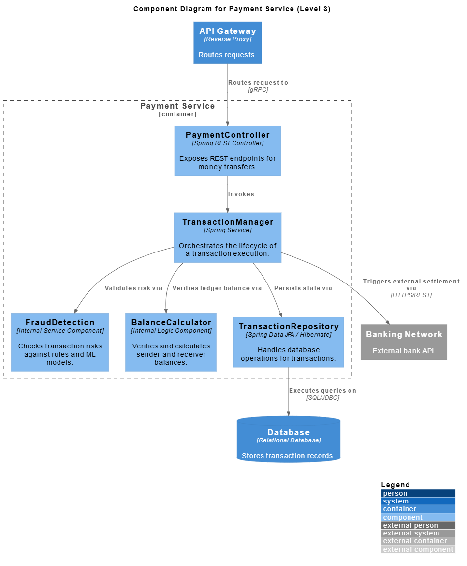
Understanding software architecture is often the most challenging part of the development lifecycle. How do we visualize the intricate relationships between different parts of a system? The answer lies in structured modeling, specifically the C4 Model. In this tutorial, we will dissect a specific Level 3 Component Diagram for a Payment Service, demonstrating how to use tools like Visual Paradigm to map out the internal logic of a complex financial application.
What is the C4 Model?
The C4 model is a hierarchical approach to software architecture documentation. It breaks down complex systems into four distinct levels of abstraction:
- Context: The high-level view of the system and its users.
- Container: The major building blocks (e.g., web apps, databases).
- Component: The internal logical components within a container.
- Code: The detailed class or function structure.
The diagram provided here focuses on Level 3: Components. This is the “engine room” view. It zooms in on a single container—the Payment Service—to show how it orchestrates transactions internally.
Analyzing the Architecture
Let’s break down the flow of data and control as depicted in the diagram, moving from the entry point down to the data storage.
1. The Entry Point: API Gateway
At the top of the diagram sits the API Gateway, labeled as a Reverse Proxy. Its job is simple but critical: it acts as the traffic cop. It receives incoming requests and routes them to the appropriate internal services. In this specific flow, it routes the payment request to our Payment Service using the gRPC protocol, which is known for its high performance in microservices communication.
2. The Container Boundary
Notice the dashed box labeled Payment Service [container]. This represents a deployable unit of software. Everything inside this box is part of our microservice. Everything outside (like the Banking Network) is external.
3. The Controller: PaymentController
Once the request enters the container, it hits the PaymentController. In a Spring Boot application, this is typically a @RestController. Its responsibility is purely to handle the HTTP request/response cycle. It exposes REST endpoints (like /api/v1/payments) and, once the request is validated, it hands off the heavy lifting to the service layer.
4. The Orchestrator: TransactionManager
The heart of the diagram is the TransactionManager. This is a @Service class that orchestrates the lifecycle of a transaction. It doesn’t do the actual work itself; instead, it coordinates other components to ensure a transaction is valid, safe, and recorded. It acts as the conductor of the orchestra, directing the other musicians.
Internal Component Interaction
The TransactionManager interacts with three distinct internal components, each handling a specific domain concern. This separation of concerns is key to maintainable code.
- FraudDetection: Before a transaction is approved, this component checks the transaction against rules and Machine Learning (ML) models. It “Validates risk via” a call to the TransactionManager.
- BalanceCalculator: This component is responsible for financial logic. It “Verifies ledger balance,” ensuring the sender has sufficient funds before the money moves.
- TransactionRepository: This component handles the persistence layer. It uses technologies like Hibernate or JPA to “Persist state” and save the transaction record to the database.
External Integrations
No payment system exists in a vacuum. The diagram shows how the service interacts with the outside world:
- Banking Network: The TransactionManager triggers an external settlement via HTTPS/REST to the Banking Network. This represents the actual transfer of funds between banks.
- Database: The TransactionRepository executes queries (SQL/JDBC) to a relational database to store the ledger state.
Visualizing the Flow
To understand this architecture programmatically, here is how you might represent the core interaction logic in a simplified Pseudo-code or PlantUML style representation:
@startuml
actor User
participant "API Gateway" as Gateway
participant "PaymentController" as Controller
participant "TransactionManager" as Manager

Controller -> Manager : Invokes processTransaction()
Manager -> Manager : ValidateRisk()
Manager -> Manager : VerifyBalance()
Manager -> Repository : Persist()
Manager -> "Banking Network" : TriggerSettlement()
@enduml
Best Practices in Component Modeling
When creating diagrams like this using tools such as Visual Paradigm, keep these principles in mind:
- Define Boundaries Clearly: Ensure the distinction between the Container and External System is obvious. Use gray boxes for external systems (like the Banking Network) to signal that you have no control over their internal implementation.
- Focus on Interaction, Not Implementation: The arrows should describe what is happening (e.g., “Validates risk”) rather than specific method names unless necessary for clarity.
- Consistent Naming: Use clear, noun-based names for components (e.g.,
FraudDetection) rather than verbs.
Conclusion
This Level 3 Component Diagram provides a clear, high-level view of the internal architecture of a Payment Service. By breaking down the system into the Controller, Manager, and supporting components, developers can easily understand the flow of data, identify dependencies, and spot potential bottlenecks. Whether you are using Visual Paradigm or drawing by hand, mastering these diagrams is essential for communicating complex system designs effectively.