
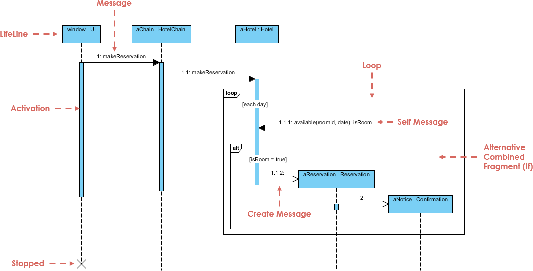
Sequence diagrams are the most widely used interaction diagrams in UML (Unified Modeling Language). They provide a detailed, chronological view of how objects communicate to perform a specific task. Unlike static diagrams that show structure, sequence diagrams show the dynamics of a system—specifically, the flow of messages between objects over time.
The Anatomy of a Sequence Diagram
To understand the diagram provided, we must first break down the fundamental elements that make up this interaction view. Every sequence diagram relies on three core concepts: lifelines, messages, and activation bars.
1. Lifelines (The Participants)
The vertical dashed lines represent lifelines. These correspond to instances of classes (objects) that participate in the interaction. In our hotel reservation example, we see the following participants:
window: UI: The User Interface, acting as the entry point.aChain: HotelChain: The business logic handler managing the hotel chain.aHotel: Hotel: The specific hotel object being queried.aReservation: Reservation: The object created to store the booking details.aNotice: Confirmation: The object responsible for notifying the user.
2. Messages (The Interaction)
Messages are the horizontal arrows connecting the lifelines. They represent method calls or signals. The diagram illustrates several types of interactions:
- Sync Message (Solid Arrow): The first interaction,
1: makeReservation, is a synchronous call from the UI to the HotelChain. - Self Message (Curved Arrow): Notice the arrow looping back to
aHotel. This is a1.1.1: available(...)call where an object invokes a method on itself. - Create Message (Dashed Arrow with ‘New’): The transition from
aHoteltoaReservationis labeled as a Create Message. This signifies that theaReservationobject is being instantiated (created) at this specific moment in time. - Return Message (Dashed Arrow): Although not explicitly labeled in every instance, the dashed lines typically imply a return value being sent back to the caller.
3. Activation Bars (Processing State)
The thin blue rectangles on the lifelines are called activation bars (or execution occurrences). They indicate the period during which an object is active—meaning it is performing an action or waiting for a response. For example, the long activation bar on aChain shows that this object is holding the control flow while delegating work to aHotel.
Advanced Modeling: Combined Fragments
Real-world logic is rarely a straight line. Sequence diagrams use Combined Fragments to handle complex control flow, such as loops and conditional logic. These are represented by the large frames surrounding specific sections of the diagram.
The Loop Fragment
Inside the loop frame, you will see the text [each day]. This indicates that the operations contained within this frame—checking availability—are repeated for every day of the requested stay. The aHotel object iterates through the dates to ensure availability.
The Alt (Alternative) Fragment
The alt frame represents a conditional branch, equivalent to an if-else statement in programming. It divides the interaction into different scenarios based on a condition:
- Condition: [isRoom = true]
- If this condition is met, the system proceeds to create a
Reservationobject and sends aConfirmationnotice. This path is labeled with the operation1.1.2.
Step-by-Step Logic Flow
- Initiation: The
window : UIsends amakeReservationrequest to theHotelChain. - Delegation: The
HotelChainforwards this request (1.1: makeReservation) to the specificHotelobject. - Verification (Loop): The
Hotelobject enters a loop, checking room availability for each day requested. It performs a self-check:available(roomId, date). - Decision (Alt): The system evaluates the result. If rooms are available (
isRoom = true), it moves to the creation phase. - Creation: The
Hotelobject creates a new instance ofReservationand aConfirmationnotice. - Termination: Once the process is complete, the activation bars disappear, and the lifeline is terminated (marked with an ‘X’), signifying the end of the interaction.
Implementing Sequence Diagrams with Visual Paradigm
To effectively model complex interactions like the hotel reservation system described above, you need robust tooling. Visual Paradigm is a premier UML tool that streamlines the creation of sequence diagrams, offering a WYSIWYG (What You See Is What You Get) environment.
Why Visual Paradigm?
Visual Paradigm simplifies the diagramming process through its intuitive drag-and-drop interface. You can easily create lifelines, define messages, and encapsulate complex logic using combined fragments like loop, alt, and opt without needing to write code manually.
Key Features for Sequence Modeling:
- Auto-Generation: You can generate sequence diagrams directly from Java or C# code, ensuring your documentation stays in sync with your actual implementation.
- Reverse Engineering: Visual Paradigm allows you to reverse engineer existing codebases into interactive sequence diagrams, making it easy to visualize legacy systems.
- Strict Syntax: The tool enforces UML standards, preventing common modeling errors and ensuring that your diagrams are readable and professional.
By leveraging Visual Paradigm, developers and architects can focus on the logic of their system—such as the intricate reservation flow we analyzed—rather than getting bogged down in the mechanics of drawing diagrams.