
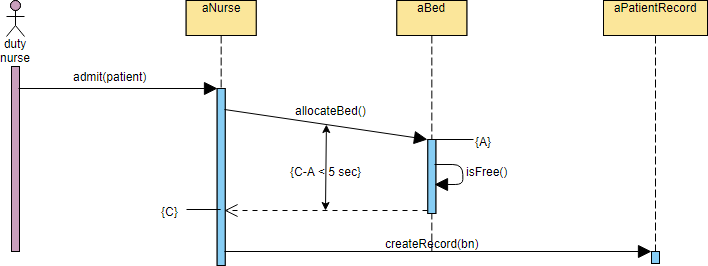
In the realm of system architecture and software engineering, a static diagram often fails to capture the true complexity of a system. It is the interaction between objects, governed by strict timing requirements, that defines a robust application. This tutorial explores the nuances of the UML Sequence Diagram, specifically focusing on how to model time-sensitive processes using Visual Paradigm.
We will analyze a critical real-world scenario: the Patient Admission Process. By breaking down this workflow, we will learn how to visualize the interaction between a nurse, a bed allocation system, and patient records, while strictly enforcing timing constraints.
Understanding the Participants
Before diving into the logic, we must define the actors and objects involved in the sequence. In Visual Paradigm, these are represented by lifelines that extend vertically from the top of the diagram.
- duty nurse (Actor): Represented by the stick figure, this is the human user initiating the request. In the system, this is the trigger for the admission workflow.
- aNurse (Object): A control object responsible for handling the nurse’s interface and coordinating the admission logic.
- aBed (Object): A critical entity object that manages bed availability. This is where the core constraint logic resides.
- aPatientRecord (Object): The persistence layer or service responsible for creating and storing the official medical record for the patient.
The Workflow: Step-by-Step
The sequence diagram illustrates a linear flow of messages (interactions) between these objects. Let’s trace the path of the admit(patient) request.
1. The Initiation
The process begins when the duty nurse invokes the admit(patient) method on the aNurse object. This is depicted by a solid arrow originating from the actor’s lifeline and pointing to the activation bar of the nurse object.
2. Bed Allocation and the Critical Constraint
Once the nurse object receives the request, it must determine if a bed is available. It sends a message to the aBed object.
Here is where the diagram becomes technically interesting. The diagram specifies a strict timing constraint: {C-A < 5 sec}.
- Message Flow: The nurse asks the bed object to allocate a bed. The bed object then calls
isFree()on itself to check its internal state. - The Constraint: The vertical double-headed arrow labeled
{C-A < 5 sec}indicates that the duration between message A (the request to allocate) and message C (the return of the result) must be strictly less than 5 seconds. This represents a system performance requirement (SLA) ensuring that the nurse does not wait too long for a response.
3. Record Creation
Once the bed is confirmed (implied by the flow continuing), the aNurse object proceeds to the final step: creating the official record. It sends a createRecord(bn) message to the aPatientRecord object, completing the admission workflow.
@startuml
actor duty_nurse
participant aNurse
participant aBed
participant aPatientRecord

duty_nurse -> aNurse: admit(patient)
activate aNurse

aNurse -> aBed: allocateBed()
activate aBed

aBed -> aBed: isFree()

note over aNurse, aBed: {C-A < 5 sec}

aBed --> aNurse: (C)
deactivate aBed

aNurse -> aPatientRecord: createRecord(bn)
deactivate aNurse
@endumlWhy Use Timing Constraints?
Many novice modelers skip timing constraints, focusing only on the logical flow of messages. However, in healthcare systems or financial transactions, time is a critical resource. By explicitly modeling the duration constraint, you communicate to developers that this interaction is time-critical. It ensures that the system architecture includes mechanisms (like timeouts or caching) to guarantee that the bed allocation check happens within the 5-second window.
Whether you are a student learning UML or a professional architect, mastering these details in Visual Paradigm ensures your diagrams are not just pictures, but precise specifications of your system’s behavior.