
Introduction: Why Class Diagrams Matter in Modern Software Development
When I first embarked on my software architecture journey, I quickly realized that clear communication between stakeholders, developers, and designers was the make-or-break factor for project success. Enter UML Class Diagrams—the visual language that transformed how I conceptualize, document, and implement object-oriented systems.
After spending considerable time with various modeling tools, I decided to document my hands-on experience with Visual Paradigm’s class diagram capabilities. Whether you’re a student learning UML fundamentals, a junior developer stepping into system design, or a seasoned architect looking to streamline your workflow, this guide shares practical insights, step-by-step techniques, and honest reflections on creating professional-grade class diagrams that actually translate to clean, maintainable code.

Getting Started: Setting Up Your First Class Diagram
Creating a New Diagram
My workflow always begins with a clean canvas. In Visual Paradigm, I navigate to Diagram > New from the application toolbar, then select Class Diagram in the New Diagram window. After clicking Next, I enter a descriptive diagram name and optional description—the Location field helps me organize diagrams within specific models. A simple OK click, and I’m ready to design.
 |
|---|
| Create class |
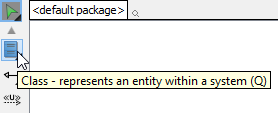
Adding Your First Class
The interface feels intuitive: I click Class on the diagram toolbar, then click anywhere on the canvas. Instantly, a class placeholder appears, ready for customization.
 |
|---|
| Class created |
Pro Tip: I always start with the class name—it’s the only mandatory element. Attributes and operations can be added incrementally as the design evolves.
Building Relationships: Connecting Classes Meaningfully
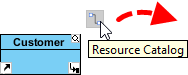
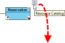
Creating Associations with the Resource Catalog
One feature I genuinely appreciate is the Resource Catalog workflow. To connect classes:
-
Hover over the source class shape
-
Press and drag the Resource Catalog button outward
 |
|---|
| Using Resource Catalog |
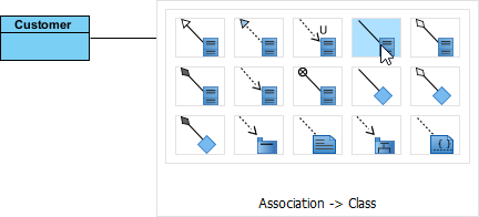
-
Release where you want the target class (drop on existing class or empty space)
-
Select Association for existing classes, or Association -> Class to create and connect a new one
-
For aggregation/composition relationships, choose the appropriate option from the catalog
 |
|---|
| To create a class |
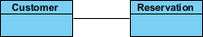
The result is a clean, connected diagram:
 |
|---|
| Associated class created |
Fine-Tuning Associations
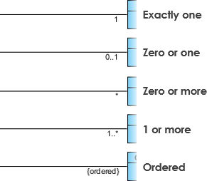
Editing Multiplicity: Right-click near an association end → Multiplicity → select the desired cardinality (1, 0..1, *, etc.)
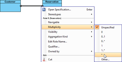 |
|---|
| Edit multiplicity |
Showing Direction: Right-click the association → Presentation Options > Show Direction to add navigational arrows
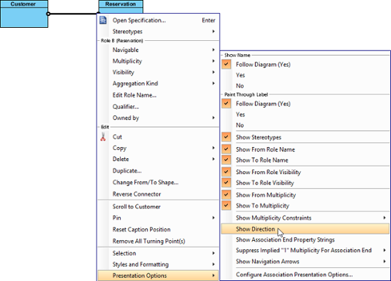 |
|---|
| Show direction |
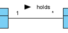 |
|---|
| Direction shown |
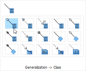
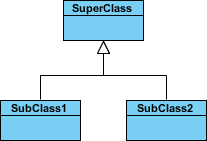
Modeling Inheritance: Generalization Relationships
Creating subclass relationships follows a similar Resource Catalog pattern:
-
Hover over the superclass
-
Drag the Resource Catalog button
-
Release at the subclass location
-
Select Generalization (for existing class) or Generalization -> Class (to create new)
 |
|---|
| Using Resource Catalog |
 |
|---|
| To create a subclass |
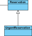 |
|---|
| Subclass created |
Design Insight: I use italics for abstract class names—a subtle but important UML convention that improves diagram readability.
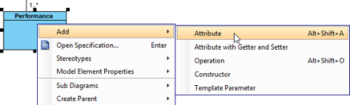
Adding Class Members: Attributes and Operations
Creating Attributes
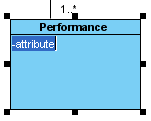
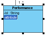
Right-click a class → Add > Attribute. The new attribute appears in the class compartment, ready for naming.
 |
|---|
| Create attribute |
 |
|---|
| Attribute created |
Efficiency Hack: After creating an attribute, press Enter to instantly add another—perfect for rapidly defining multiple properties.
 |
|---|
| Create attribute with Enter key |
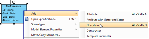
Creating Operations
Same workflow: Right-click class → Add > Operation
 |
|---|
| Create operation |
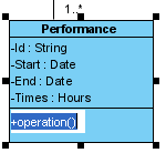 |
|---|
| Operation created |
Parameter Tip: When a parameter name starts with unnamed_, Visual Paradigm displays only its type—cleaner diagrams for internal implementation details.
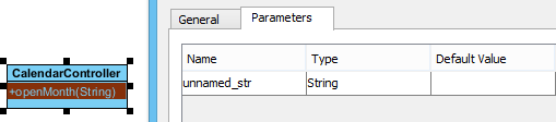 |
|---|
| Unnamed parameter |
Managing Class Members: Drag, Drop, and Organize
Reordering Members
Select any attribute or operation, then drag within its compartment. A thick black line indicates the drop position.
 |
|---|
| Reorder class member |
 |
|---|
| Class member reordered |
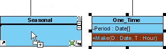
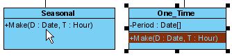
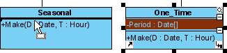
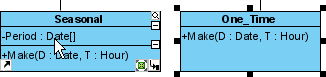
Copying vs. Moving Members
-
Copy: Select member → drag to target class while holding Ctrl (cursor shows +)
-
Move: Select member → drag to target class without modifier keys
 |
|---|
| Copy class member |
 |
|---|
| Class member copied |
 |
|---|
| Move class member |
 |
|---|
| Class member moved |
Productivity Boost: Press Alt+A after selecting one member to select all members within a class—ideal for bulk operations.
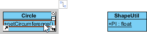
Advanced Relationships: Dependencies Between Members
Dependencies aren’t limited to whole classes. I frequently model relationships between specific attributes or operations:
-
Select Dependency from the diagram toolbar
-
Click and hold on the source member (attribute/operation)
-
Drag to the target member
-
Release to create the connector
 |
|---|
| Selecting Dependency |
 |
|---|
| To press on the source operation |
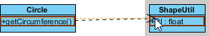 |
|---|
| Dragging to target attribute |
 |
|---|
| Dependency created between an operation and a member |
Important Note: Though connectors visually attach to class boundaries, checking the specification confirms they link the precise members—critical for accurate code generation.
Specialized Class Types: Enumerations and Delegates
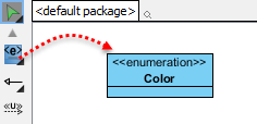
Creating Enumerations
For predefined value sets (Color: RED/GREEN/BLUE, Status: ACTIVE/INACTIVE):
-
Select Enumeration from the toolbar
-
Click on the diagram canvas
 |
|---|
| Create an enumeration |
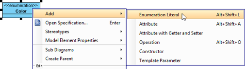
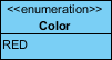
Add literals via right-click → Add > Enumeration Literal
 |
|---|
| Add an enumeration literal |
 |
|---|
| Enumeration literal entered |
Delegate Methods (C#/VB.NET Projects)
When targeting .NET languages, I can stereotype classes as delegates: Right-click class → Stereotypes > Delegate
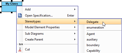 |
|---|
| Stereotype class as Delegate |
Controlling Visibility: Hiding and Showing Details
Three Levels of Control
I appreciate Visual Paradigm’s flexible presentation options:
Per Workspace (global defaults):
Window > Project Options > Diagramming > Class > Presentation
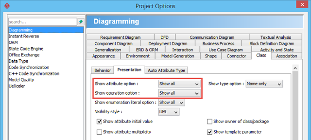 |
|---|
| Show or hide operations |
Per Diagram: Right-click diagram → Presentation Options > Attribute/Operation Display Options
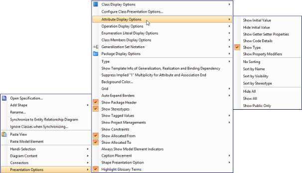 |
|---|
| Change the operations’ presentation options for classes in diagram |
Per Class: Right-click class → Presentation Options > Attributes/Operations
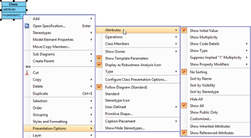 |
|---|
| Change the operations’ presentation options for a class |
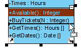
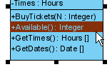
Granular Control: For specific members, use Customized… to selectively show/hide individual attributes or operations
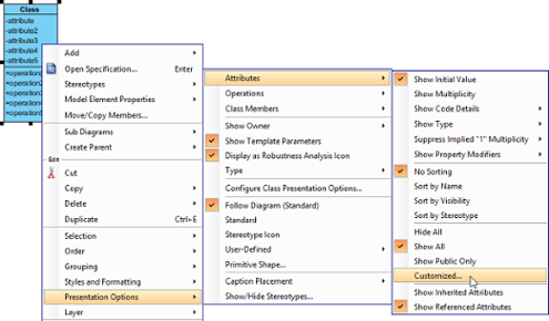 |
|---|
| Show or hide specific class member |
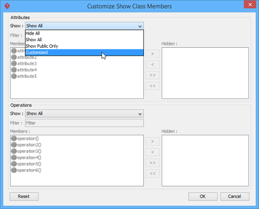 |
|---|
| Select Customized in window |
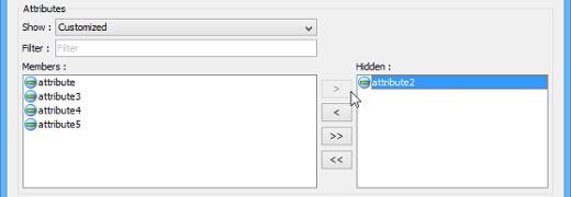 |
|---|
| Select attributes to hide |
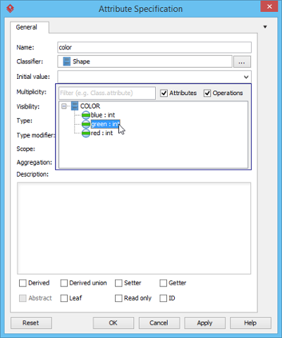
Setting Default Values and Advanced Association Features
Initial Attribute Values
To define default values:
-
Right-click attribute → Open Specification…
-
In the General tab, enter a text value or select a public static field from another class
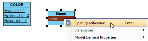 |
|---|
| Opening the attribute specification |
 |
|---|
| Selecting an initial value |
Note: To reference another class’s attribute as a default value, ensure that attribute is both
static(classifier scope) andpublic.
Association End Ownership
Indicate ownership with a small dot: Right-click association end → Owned by → select the owning class
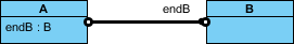 |
|---|
| Association end with ownership set |
Subsetting on Association Ends
For complex domain models, subsetting clarifies collection relationships:
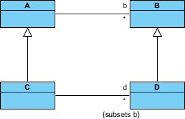 |
|---|
| Subsetting on association end |
Configuration requires opening the association specification and defining subsetted ends in the Association End Specification window.
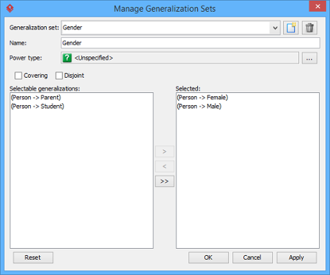
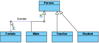
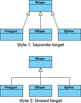
Generalization Sets: Organizing Inheritance Hierarchies
When multiple generalizations share common constraints, I group them into generalization sets:
-
Select relevant generalization connectors
-
Right-click → Generalization set > Create Generalization Set…
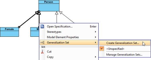 |
|---|
| Create a generalization set |
-
Name the set in the dialog and confirm
 |
|---|
| Name the generalization set |
-
Adjust connectors for visual clarity
 |
|---|
| Adjust connector |
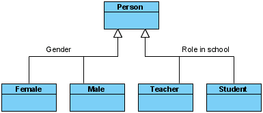 |
|---|
| Generalization sets defined |
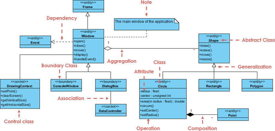
Understanding UML Class Fundamentals: A Quick Reference
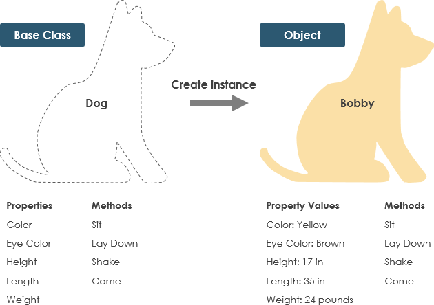
What Is a Class?
A class is a blueprint for objects. While objects are runtime instances, classes define their structure and behavior. For example, a Dog class specifies properties (color, name, breed) and behaviors (bark(), eat()), while individual dogs are objects instantiated from that blueprint.
Class Notation Essentials
A UML class rectangle has three compartments:
-
Class Name (mandatory, bold)
-
Attributes (name: type, with visibility symbols)
-
Operations (method(parameters): returnType)
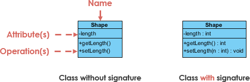
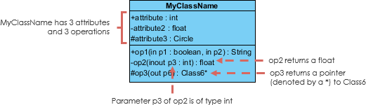
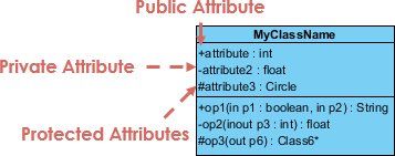
Visibility Symbols
-
+Public: accessible everywhere -
-Private: accessible only within the class -
#Protected: accessible within class and subclasses
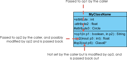
Parameter Directionality
Parameters can specify data flow: in, out, or inout
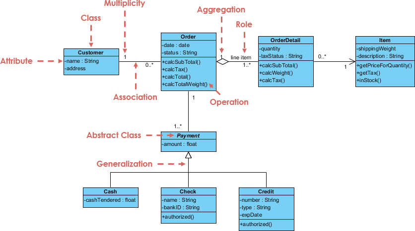
Relationship Types Decoded: From Association to Realization
Inheritance (Generalization)
Represents “is-a” relationships. Subclasses inherit features from superclasses.
Association Types
Simple Association: Structural link between peer classes
Cardinality: Expresses multiplicity (1, 0..1, , 1..)
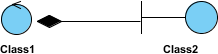
Aggregation: “Has-a” relationship with independent lifetimes (unfilled diamond)

Composition: Strong “part-of” relationship; parts die with whole (filled diamond)
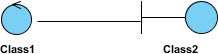
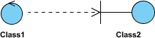
Dependency: Usage relationship; changes to supplier may affect client (dashed arrow)

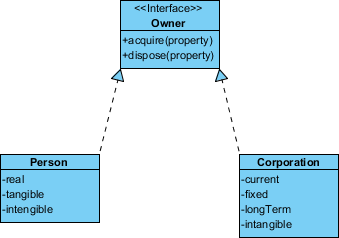
Realization: Interface implementation contract (dashed line with hollow arrowhead)
Practical Examples: Learning by Doing
Order System Diagram
A comprehensive example showing products, customers, orders, and payment processing:
GUI Component Diagram
Demonstrates notes, stereotypes, and interface relationships in a user interface context:
My Perspective: Choosing the Right Diagram Detail Level
The perspective you adopt dramatically impacts diagram utility:
| Perspective | Best For | Detail Level |
|---|---|---|
| Conceptual | Domain modeling, stakeholder discussions | High-level concepts, minimal technical detail |
| Specification | Interface design, API contracts | Focus on operations, visibility, parameter types |
| Implementation | Code generation, developer handoff | Full attributes, methods, visibility, constraints |
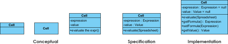
My Approach: I start conceptual during discovery, evolve to specification during design sprints, and refine to implementation details only when generating code or onboarding new developers.
Accelerating Learning with AI-Powered Tools
Visual Paradigm’s AI ecosystem has transformed my diagramming workflow:
Integrated Platforms
-
VP Desktop: Full-featured editing with AI-assisted generation
-
AI Chatbot: Conversational diagram drafting at chat.visual-paradigm.com
-
OpenDocs: Embed class diagrams directly in technical documentation
Specialized AI Applications
✨ AI Class Diagram Wizard: Step-by-step class creation with AI-suggested members
📋 Use Case Studio: Auto-extract domain classes from use case text
🏃 Agilien: Generate diagrams from Agile epics and user stories
🗄️ DB Modeler AI: Bridge conceptual models to database schemas
🏗️ MVC Architecture: Visualize controller responsibilities
Conclusion: From Diagrams to Deliverables
After months of iterative use, I can confidently say that mastering UML class diagrams in Visual Paradigm has elevated both my design thinking and team collaboration. The tool’s balance of visual intuitiveness and technical precision bridges the gap between abstract architecture and concrete implementation.
My key takeaways for fellow practitioners:
-
Start simple: Focus on class names and core relationships before adding detail
-
Leverage perspectives: Match diagram detail to your audience and development phase
-
Embrace automation: Use AI tools for initial drafts, then refine manually for precision
-
Document decisions: Add notes to clarify non-obvious design choices
-
Iterate continuously: Treat diagrams as living artifacts that evolve with your codebase
Whether you’re modeling a microservice architecture, documenting a legacy system, or teaching object-oriented principles, class diagrams remain an indispensable communication tool. With Visual Paradigm’s robust feature set and growing AI capabilities, the barrier to creating professional, actionable diagrams has never been lower.
The journey from blank canvas to executable design specification is challenging—but with the right tools and mindset, it’s also deeply rewarding. Happy modeling!
References
- What is Class Diagram? – Visual Paradigm Features: Overview of class diagram capabilities within Visual Paradigm’s UML tool suite.
- Visual Paradigm UML Tool Features: Comprehensive listing of UML diagram types and modeling features supported by Visual Paradigm.
- What is Class Diagram? – Introductory Guide: Beginner-friendly explanation of class diagram concepts, notation, and use cases.
- Visual Paradigm Tutorials: Collection of step-by-step tutorials to help users get started with Visual Paradigm and UML modeling.
- Visual Paradigm YouTube Channel: Video tutorials, product demos, and modeling best practices from the Visual Paradigm team.
- Visual Paradigm Know-How: Community-driven knowledge base with tips, tricks, and solutions to common modeling challenges.
- Visual Paradigm Support: Official support portal for product assistance, documentation, and feature requests.
- Unified Modeling Language – Wikipedia: Encyclopedic overview of UML history, diagram types, and standardization.
- Visual Paradigm Community Edition Download: Free download page for the community edition of Visual Paradigm, supporting all UML diagram types.
- Visual Paradigm AI Chatbot: Conversational AI interface for drafting and refining UML diagrams through natural language prompts.
- OpenDocs – AI-Powered Documentation: Tool for creating and embedding AI-generated class diagrams within technical project documentation.
- AI Class Diagram Wizard: Dedicated wizard for building UML class diagrams with AI-suggested attributes, operations, and relationships.
- Use Case Studio: AI tool that automatically identifies domain classes and relationships from use case descriptions.
- Agilien – Agile to Design: Platform for generating class diagrams directly from Agile epics, user stories, and sprint planning artifacts.
- DB Modeler AI: AI-powered tool for creating conceptual class diagrams that serve as the foundation for database schema generation.
- MVC Architecture Generator: Specialized AI tool for generating Controller class diagrams to visualize system responsibilities in MVC architectures.