
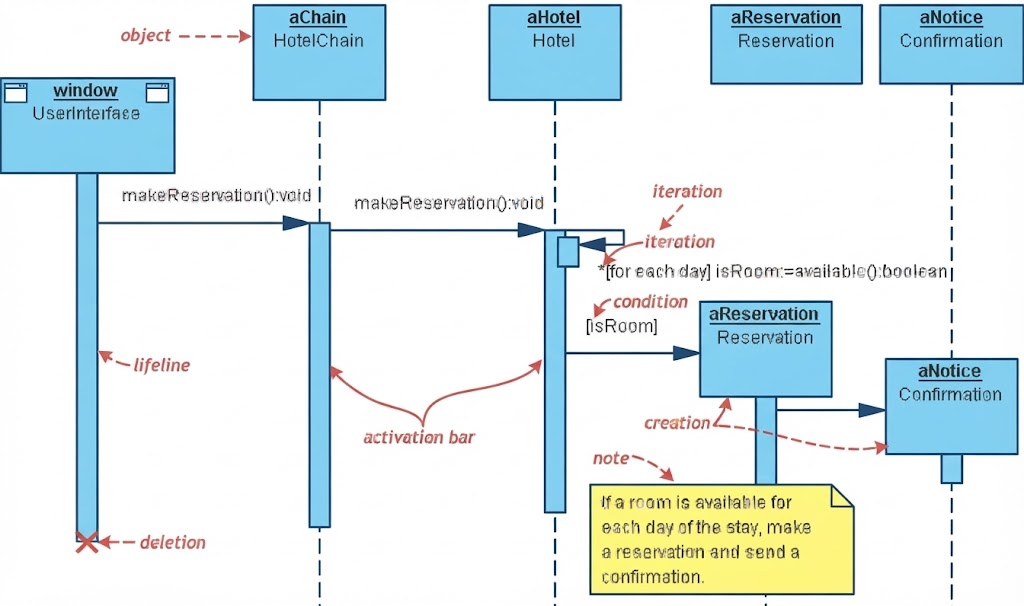
Unified Modeling Language (UML) sequence diagrams are more than just technical drawings; they are the narrative blueprints of software architecture. They tell the story of how data moves between objects, who triggers which action, and how the system responds to user intent. In this tutorial, we will dissect a classic example: an automated hotel room booking workflow. By analyzing the interactions between a user interface, a hotel chain, and reservation logic, we will uncover the precise mechanisms that drive complex system logic.
Understanding the Core Participants
Every sequence diagram relies on “Lifelines” to represent the participants in the interaction. In our hotel booking scenario, the model coordinates five distinct object instances, each playing a critical role in the transaction:
- window (UserInterface): The entry point for the user. This object initiates the booking request.
- aChain (HotelChain): The orchestrator. This object represents the overarching chain managing multiple hotels.
- aHotel (Hotel): The specific entity being queried. This object holds the logic for room availability.
- aReservation (Reservation): The transaction handler. This object manages the actual booking data.
- aNotice (Confirmation): The output generator. This object handles the creation of booking confirmations.
Visualizing the Message Flow
The heart of the diagram lies in the arrows connecting these lifelines. These arrows represent messages—requests or data transfers—passed chronologically from left to right.
1. Initiation and Delegation
The process begins when the window sends a makeReservation():void message to the aChain object. This is a standard delegation pattern: the user interface doesn’t handle the complex logic itself; it delegates the responsibility to the system’s controller. The aChain object receives this message and, in turn, forwards a makeReservation():void message to the specific aHotel instance.
2. Iteration and Availability Checks
Once the hotel receives the request, it must determine if the requested dates are valid. The diagram features a powerful construct here: an iteration (loop). The label *{for each day} isRoom:=available():boolean indicates that the system iterates through the requested stay, checking availability for every single day. This ensures that a reservation is only made if the room is available for the entire duration.
3. Conditional Logic
Following the loop is a condition guard, denoted by [isRoom]. This is a critical decision point. The logic dictates that the flow only proceeds to the next step if the condition evaluates to true (i.e., the room is available). If the room is not available, this branch of the sequence terminates, preventing an invalid booking.
Object Lifecycle: Creation and Deletion
Sequence diagrams also track the creation and destruction of objects. In this model, we see a creation event where the aReservation object (or a specific confirmation object) is instantiated. A dashed arrow with an open arrowhead points from the active object to the new object, signifying that the system is “spawning” a new instance of aNotice to handle the confirmation.
Conversely, the diagram shows a deletion event at the bottom of the window lifeline. The “X” mark indicates that the user interface context or the specific session object is being destroyed after the transaction is complete, cleaning up system resources.
Visual Elements Breakdown
To read these diagrams effectively, you must understand the specific visual cues used in Visual Paradigm:
- Activation Bar: The vertical rectangles on the lifelines represent the period during which an object is actively performing an operation. Notice how the bar on aHotel extends while it checks availability and how the bar on aReservation appears only when the condition is met.
- Note: The yellow sticky note attached to the aHotel lifeline provides a business rule context: “If a room is available for each day of the stay, make a reservation and send a confirmation.”
Tooling: Visual Paradigm for the Article
While many tools exist for UML modeling, Visual Paradigm offers a specialized environment for creating robust sequence diagrams. Its interface allows for precise control over the timing of messages and the layout of lifelines, ensuring that the diagram remains readable even as complexity grows.
When modeling complex logic like the iteration loop seen in our hotel example, Visual Paradigm allows you to group these elements into a single “Loop” fragment. This keeps the diagram clean by hiding the repetitive nature of the day-by-day check, showing only the summary of the action. Furthermore, the tool’s syntax highlighting for OCL (Object Constraint Language) and Java snippets helps developers write precise logic within the diagram notes, bridging the gap between design and development.
By mastering these concepts, you move beyond simple drawing to true architectural design. You are no longer just depicting a flow; you are defining the rules of engagement for your software system.