
Introduction: Why Use Case Diagrams Matter (And Why I Finally Took the Plunge)
As a product professional who’s worn many hats—from business analyst to systems designer—I’ve long understood the theoretical value of use case diagrams. But actually creating them? That always felt like a chore reserved for “real” modelers with expensive enterprise tools.
Last quarter, my team needed to document requirements for a new customer portal. Stakeholders were talking past each other, scope was creeping, and our user stories felt disconnected. That’s when I decided to finally learn use case modeling properly. After testing several tools, I settled on Visual Paradigm—and honestly, it changed how I approach requirements gathering.

This isn’t a dry technical manual. This is my real-world experience learning to draw professional use case diagrams, complete with the wins, the “aha!” moments, and the practical tips I wish someone had shared with me on day one.
Getting Started: Creating Your First Use Case Diagram
Setting Up the Canvas
When I first opened Visual Paradigm, I appreciated how straightforward the setup was. No overwhelming menus or cryptic wizards. Here’s exactly what I did:
-
Selected Diagram > New from the application toolbar
-
In the New Diagram window, chose Use Case Diagram
-
Clicked Next, entered a meaningful diagram name (“Customer Portal – Core Functions”), and selected where to store it
-
Clicked OK and—just like that—I had a clean canvas ready for modeling
 |
|---|
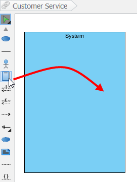
| Create a system |
Drawing the System Boundary
One feature that immediately clicked for me was the System element. Drawing a boundary box around my use cases helped me—and my stakeholders—visually separate what’s inside our application scope versus external actors.
To create it: Select System on the diagram toolbar, click on the canvas, and name it immediately. I named mine “Customer Portal System.” This simple step prevented countless scope discussions later!
Adding Actors: Who Interacts With Your System?
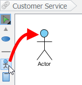
Actors are the human (or system) faces of your requirements. I started with “Customer,” “Support Agent,” and “Payment Gateway.”
To draw an actor: Select Actor on the toolbar, click on the diagram pane, and name it when prompted.
 |
|---|
| Create an actor |
Pro tip from my experience: Don’t overcomplicate actors early on. Start with primary users, then refine. I initially added “Admin,” “Guest,” and “API Consumer”—but merged some after realizing they shared identical interactions.
Building Use Cases: From Ideas to Visual Requirements
The Fast Way: Resource Catalog Magic
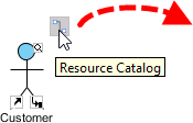
Early in my learning curve, I was manually dragging use cases and then connecting them. Then I discovered the Resource Catalog—a game-changer for rapid modeling.
Here’s the workflow that saved me hours:
-
Hover over a source shape (like an actor)
-
Press the Resource Catalog button (small icon at shape’s edge) and drag outward
-
Release at your preferred location
-
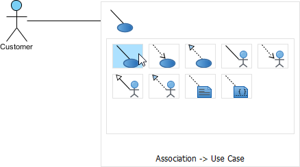
Select Association -> Use Case from the catalog
 |
|---|
| Resource Catalog |
 |
|---|
| To create a use case |
 |
|---|
| Use Case created |
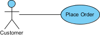
The tool automatically connects the actor to the new use case. I named mine “Place Order,” “View Order History,” and “Update Profile.” Instant visual requirements!
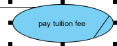
Handling Long Use Case Names
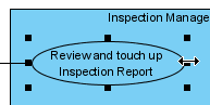
Real-world use cases often have descriptive names. When “Generate Monthly Usage Report” made my oval comically wide, I learned two tricks:
-
Resize manually: Drag the filled selectors on the use case border—the name auto-wraps
-
Force line breaks: Press Alt + Enter where you want a new line
 |
|---|
| Resize a use case |
| NOTE: | Alternatively, you can press Alt + Enter to force a new line. |
|---|
Modeling Complex Relationships: Include, Extend, and Beyond
The <<Extend>> Relationship: Optional Behavior
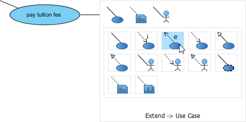
When modeling “Apply Promo Code” as an optional step during checkout, I needed an extend relationship. Here’s how I built it:
-
Hover over the base use case (“Place Order”)
-
Drag out its Resource Catalog button
-
Release at preferred location and select Extend -> Use Case
-
Name the new use case (“Apply Promo Code”) and define the extension point
 |
|---|
| Create an extend relationship |
My insight: Extension points clarify where optional behavior injects. I labeled mine “after payment method selection”—making the model self-documenting for developers.
The <<Include>> Relationship: Reusable Steps
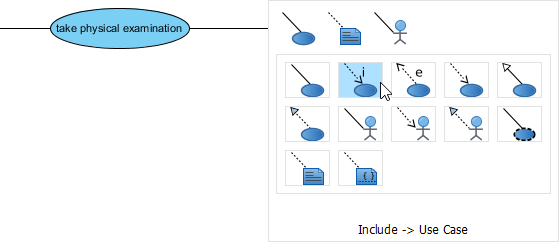
For “Validate User Credentials” (used by Login, Password Reset, and Profile Update), the include relationship prevented duplication:
-
Same Resource Catalog workflow
-
Select Include -> Use Case
-
Name the shared use case
 |
|---|
| Include relationship is created |
Lesson learned: Use include for mandatory, reusable steps. Save extend for conditional/optional behavior. Mixing them up confused my initial diagrams!
Organizing Complexity: Packages and Business Modeling
Grouping with Packages
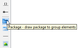
When my diagram grew to 15+ use cases, visual clutter became a problem. Packages saved the day:
-
Select Package on the toolbar
-
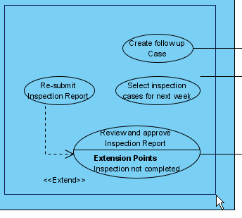
Drag to create a container around related use cases
-
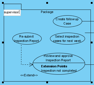
Name it meaningfully (“Order Management,” “User Account”)
 |
|---|
| Create a package |
 |
|---|
| Surround use cases with package |
 |
|---|
| Name the package |
Business Use Cases: Bridging Business and IT
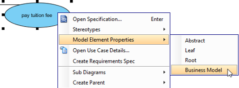
For stakeholder workshops, I needed to distinguish business goals from system functions. Visual Paradigm makes this simple:
-
Right-click a use case → Model Element Properties > Business Model
-
An extra slash appears on the use case’s left edge, marking it as business-focused
 |
|---|
| Click Business Model |
 |
|---|
| Business Model |
Why this mattered: During executive reviews, business use cases (“Increase Customer Retention”) sparked strategy conversations, while system use cases (“Send Re-engagement Email”) drove technical planning.
Beyond the Diagram: The Features That Changed My Workflow
Flow of Events Editor
A use case oval is just the headline. The real value came from documenting how each scenario unfolds. Right-clicking a use case → Use Case Details opened a structured editor where I:
-
Listed step-by-step user actions
-
Added system responses
-
Attached wireframes to specific steps
Requirements Traceability
I linked each use case to business requirements in Visual Paradigm’s Requirements List. When stakeholders asked, “Why are we building this feature?” I could instantly show the trace to a business goal. No more “because the CEO said so” debates.
AI-Powered Generation (The Future is Here!)
For greenfield projects, I experimented with Visual Paradigm’s AI tool:
-
Described my system in plain English: “E-commerce platform where customers browse products, manage carts, and checkout securely”
-
Clicked generate—and got a starter diagram in seconds
-
Used the Refine button to explore alternative relationship structures
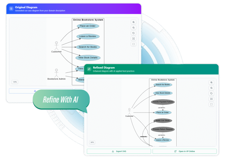
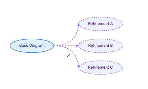
My take: AI won’t replace thoughtful modeling, but it’s incredible for overcoming blank-canvas paralysis. I used it for first drafts, then refined manually.
Collaboration & Delivery: Sharing Your Model with Confidence
Publishing for Stakeholders
Instead of exporting static PNGs, I published diagrams to Visual Paradigm’s online viewer. Stakeholders could:
-
View diagrams from any device
-
Leave contextual comments directly on elements
-
See version history and change rationale
Export Flexibility
When I needed diagrams for documentation:
-
Exported as high-quality SVG for presentations
-
Generated Word/PDF reports with use case specifications
-
Opened models in Visual Paradigm Online for team editing
Team Collaboration Features
Working with remote teammates, I appreciated:
-
Smart conflict resolution when multiple people edited
-
Branch/merge for parallel feature modeling
-
Visual comparison tools to review changes between versions
My Honest Assessment: Strengths and Considerations
What I Loved ✅
-
Intuitive drag-and-drop: No steep learning curve for core diagramming
-
All-in-one approach: Diagrams, documentation, and requirements in one tool
-
Standards compliance: UML notation that developers actually recognize
-
AI assistance: Genuinely useful for ideation, not just marketing hype
-
Export flexibility: From quick PNGs to formal specification documents
Areas for Growth ⚠️
-
Initial setup: The full desktop app has many features—new users might benefit from a “simple mode”
-
Mobile viewing: Online viewer works well, but mobile editing remains limited
-
Pricing: Enterprise features require paid plans (though the free tier is generous for learning)
Who Is This For?
-
Product Managers: Clarify scope and communicate requirements visually
-
Business Analysts: Bridge stakeholder needs and technical implementation
-
Developers: Understand system interactions before coding begins
-
Students: Learn UML with a tool that enforces proper notation
Conclusion: From Skeptic to Advocate
Six months ago, I viewed use case diagrams as academic exercises. Today, they’re central to how my team aligns on requirements, prioritizes features, and communicates with stakeholders.
Visual Paradigm didn’t just give me a diagramming tool—it provided a requirements thinking framework. The ability to move seamlessly from a high-level actor/use case overview down to detailed flow-of-events documentation transformed how I capture and socialize product vision.
If you’re on the fence about investing time in use case modeling: start small. Model one core user journey. Share it with a developer and a stakeholder. Notice how much clearer the conversation becomes. That’s the real value—not perfect diagrams, but shared understanding.
And if you choose Visual Paradigm (as I did), leverage its learning resources. The YouTube tutorials, community forums, and AI assistant accelerated my journey from novice to confident practitioner.
Your system’s complexity doesn’t have to mean chaotic requirements. With the right approach—and the right tool—you can turn ambiguity into actionable clarity, one use case at a time.
References
- What is Use Case Diagram? – An introductory guide to Use Case Diagram: A foundational guide explaining the purpose, components, and benefits of UML use case diagrams for system modeling.
- How to Identify Business Goals of an IT System: A tutorial on aligning use case modeling with business objectives to ensure technical features serve clear purposes.
- Beginner’s Guide to Use Case Diagrams with Visual Paradigm Online: A step-by-step blog post for newcomers to create use case diagrams using Visual Paradigm’s online tools.
- User’s Guide – Drawing a Use Case Diagram: Official Visual Paradigm documentation detailing the technical steps for creating use case diagrams within the software.
- Writing Effective Use Cases Tutorial: A guide on documenting use case scenarios, flow of events, and linking wireframes to enhance requirement clarity.
- Use Case Diagram Notations Guide: Comprehensive reference for UML notation standards including actors, use cases, include/extend relationships, and system boundaries.
- Visual Paradigm Use Case Tool Solution Page: Overview of Visual Paradigm’s dedicated use case modeling features, including flow of events, notes editor, and requirements management.
- YouTube: Use Case Diagram Tutorial: Video walkthrough demonstrating practical use case diagram creation techniques.
- YouTube: AI-Powered Use Case Generation: Demonstration of Visual Paradigm’s AI tools for automatically generating use case diagrams from text descriptions.
- YouTube: Advanced Use Case Modeling Techniques: Advanced tutorial covering complex relationships, extension points, and model refinement strategies.
- Documenting Use Cases – User Guide: Official documentation on using Visual Paradigm’s features to document use case details, notes, and requirements traceability.