
Designing a complex system requires a shared language that transcends code and documentation. A profile diagram serves as that critical visual interface, bridging the gap between abstract requirements and concrete implementation. Whether you are mapping out a software ecosystem, defining an organizational hierarchy, or outlining a user journey, the starting point is always the right template. Choosing the correct structural foundation ensures that every subsequent design decision rests on a solid framework. This guide explores the essential aspects of profile diagramming, offering a clear path from initial concept to finalized model without relying on specific proprietary tools.
Understanding the Profile Diagram 📐
At its core, a profile diagram is a specialized view used to define the context and boundaries of a system. It does not necessarily detail every internal function but rather focuses on the external relationships and the high-level structure. This abstraction allows stakeholders to understand the “what” and “where” before diving into the “how”.
Definition and Core Purpose
The primary purpose of this diagram type is to establish a shared vocabulary among team members. When a developer, a product manager, and a stakeholder look at the same model, they need to see the same relationships. A well-constructed template ensures that:
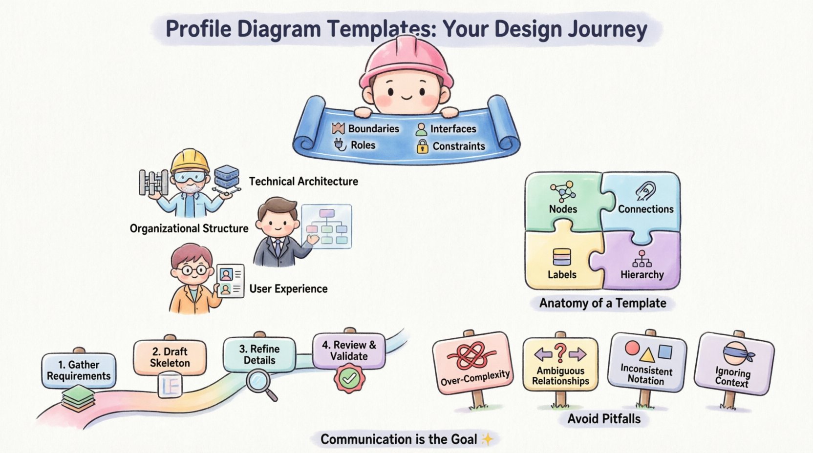
- Boundaries are clear: It explicitly states what is inside the system and what lies outside.
- Interfaces are defined: It highlights where data or control flows enter and exit the model.
- Roles are identified: It distinguishes between the entities that interact with the system and the system itself.
- Constraints are visible: It shows limitations or dependencies that affect the design.
Differentiating from Other Diagram Types
It is common to confuse profile diagrams with flowcharts or network maps. While a flowchart describes a sequence of events, a profile diagram describes a state of existence. It is less about movement and more about structure. Unlike a network map that focuses on physical connectivity, a profile diagram focuses on logical connectivity. This distinction is vital when selecting a template, as using a flowchart template for a structural overview can lead to confusion regarding static relationships versus dynamic processes.
Selecting the Right Template Framework 🛠️
Not all diagrams are created equal. The choice of template depends heavily on the domain you are modeling. A template designed for software architecture may not fit an organizational chart, and vice versa. Below is a breakdown of common categories and their specific applications.
Technical Architecture Profiles
These templates focus on the infrastructure and logical components of a technical system. They are essential for engineering teams who need to visualize how different modules interact. Key elements often include:
- Server nodes and client devices
- Database schemas and storage layers
- API gateways and middleware
- Security zones and trust boundaries
Organizational Structure Profiles
In business contexts, these diagrams map out departments, teams, and reporting lines. They help clarify decision-making hierarchies and communication channels. When using this template, focus on:
- Roles and responsibilities
- Communication flows between departments
- Resource allocation and ownership
- External partners and vendors
User Experience and Interface Profiles
For product design, the profile diagram outlines the touchpoints a user has with a system. It is less about backend logic and more about the human interaction layer. Elements typically include:
- User personas and their goals
- Interface screens or portals
- Interaction points and feedback loops
- Content delivery mechanisms
Comparison of Template Types
| Template Category | Primary Focus | Key Audience | Typical Complexity |
|---|---|---|---|
| Technical Architecture | System Components | Engineers, Architects | High |
| Organizational Structure | Human Resources | Management, HR | Medium |
| User Experience | Interaction Design | Designers, Product Owners | Medium-High |
| Business Process | Workflow Logic | Analysts, Operations | High |
Anatomy of a Robust Template 🧩
Regardless of the category, a high-quality profile diagram shares a common anatomical structure. Understanding these components allows you to build or select a template that supports clarity and scalability.
Nodes and Connections
Nodes represent the entities within your model. They can be physical devices, logical modules, people, or abstract concepts. Connections represent the relationships between these nodes. The visual weight of these elements matters. Stronger lines usually indicate critical dependencies, while dashed lines might suggest optional or secondary interactions. Consistency in line style is non-negotiable for readability.
Labels and Annotations
Text is often the most critical part of a diagram. Labels must be concise yet descriptive. Avoid using labels that require interpretation. If a connection is labeled “Data Flow,” specify the type of data if relevant. Annotations provide context that cannot be visualized through shapes alone. They are useful for explaining constraints, assumptions, or specific business rules associated with a node.
Hierarchy and Grouping
Large systems cannot exist as a flat list of nodes. Grouping allows you to bundle related components into sub-systems. This creates a hierarchy that can be expanded or collapsed during review. For example, a “Security Layer” might contain multiple nodes like “Firewall,” “Auth Server,” and “Logging Service.” This nesting helps manage complexity without losing detail.
Step-by-Step Design Process 📝
Creating a profile diagram is not merely about drawing shapes. It is a structured process of discovery and refinement. Following a phased approach ensures that the final output accurately reflects the reality of the system.
Phase 1: Requirements Gathering
Before opening any canvas, you must understand the scope. What is the problem being solved? Who are the users or actors? What are the hard constraints? This phase involves interviews, document review, and brainstorming. The goal is to list every element that must be represented. Do not worry about the layout yet; focus on the inventory of components.
Phase 2: Drafting the Skeleton
Begin with the largest components. Place the system boundary first. Then, add the primary actors or external systems. At this stage, ignore fine details. Use simple rectangles or circles to represent nodes. Draw the primary connections. This skeleton establishes the topology. If the skeleton feels unbalanced or confusing, the detailed work later will be futile. Adjust the high-level structure before adding decoration.
Phase 3: Refinement and Detailing
Once the skeleton is stable, add the layers of detail. Define the sub-groups. Add labels to every connection. Specify the data types or protocols if relevant to the context. Ensure that all nodes have a clear definition. This is where the template choices matter most. If you chose a technical template, ensure the shapes match the architectural patterns you are using.
Phase 4: Review and Validation
Never publish a diagram without a review cycle. Walk through the model with a peer who did not create it. Ask them to trace a path from start to finish. If they get stuck, the diagram is not clear. Check for orphaned nodes that have no connections. Verify that the boundaries make sense. Validation is about correctness, not just aesthetics.
Common Structural Pitfalls ⚠️
Even experienced modelers fall into traps that degrade the utility of a diagram. Being aware of these common issues helps you avoid them from the start.
Over-Complexity
There is a tendency to include every possible detail in the initial draft. This leads to a “spaghetti diagram” where lines cross chaotically. To combat this, consider layering. Create a high-level overview first, then link to detailed sub-diagrams for specific areas. A single page should not try to explain the entire enterprise architecture.
Ambiguous Relationships
A line between two boxes is not enough information. Does the relationship imply ownership? Data flow? Control signal? Authorization? If the meaning is not clear, the diagram fails. Use distinct arrowheads or line styles to denote direction and type of relationship. Always define the legend if you use non-standard symbols.
Inconsistent Notation
Using a circle for a database in one section and a cylinder in another creates cognitive friction. Users should not have to guess what a shape means. Adhere strictly to the notation rules defined by the template or the modeling standard you are following. Consistency builds trust in the documentation.
Ignoring the Context
A diagram is always viewed in a specific context. A diagram meant for developers might look different from one meant for executives. Executives need to see value and flow; developers need to see structure and interfaces. Tailor the template and the level of detail to the intended audience. Do not create a “one size fits all” diagram for all stakeholders.
Collaboration and Iteration 🤝
Profile diagrams are rarely finished in a single session. They are living documents that evolve as the system changes. Collaboration tools and processes are essential for this lifecycle.
- Version Control: Treat the diagram like code. Keep track of changes. Maintain a history of revisions so you can revert if a change breaks the logic.
- Comments and Feedback: Enable a mechanism for stakeholders to leave notes directly on the model. This keeps the feedback contextual and actionable.
- Access Permissions: Define who can edit and who can only view. Core architects should have edit rights, while other team members might only have view access to prevent accidental corruption.
- Export Formats: Ensure the diagram can be exported in formats suitable for documentation, presentations, and code generation if needed.
Maintaining Diagram Integrity Over Time 🔄
One of the biggest challenges in system modeling is keeping the diagram up to date. As software changes, requirements shift, and infrastructure evolves, the diagram becomes a liability if it does not reflect reality. To maintain integrity:
- Link to Artifacts: Where possible, link diagram nodes to specific requirements or code modules. This creates a traceability chain.
- Schedule Reviews: Make diagram updates part of the sprint or release cycle. Do not wait for a crisis to realize the map is wrong.
- Archive Old Versions: Keep historical diagrams for reference. They explain why a system was designed a certain way, which is valuable for future onboarding.
Integrating with Documentation 📚
A profile diagram should never exist in isolation. It is a visual anchor within a larger body of documentation. When integrating:
- Table of Contents: Ensure the diagram is referenced in the main index. It should be easy to find.
- Contextual Text: Surround the image with text that explains it. Do not assume the visual speaks for itself.
- Cross-References: Link to other diagrams. A profile diagram might link to a detailed sequence diagram for a specific component.
Conclusion
Starting your design journey with the right profile diagram templates sets the stage for clarity and efficiency. By understanding the anatomy of these models, selecting the appropriate framework for your context, and adhering to a disciplined design process, you create assets that serve the team effectively. Avoiding common pitfalls like over-complication and ambiguity ensures that the diagram remains a useful tool rather than a decorative artifact. As you move forward, remember that the goal is communication. A diagram that is understood is a diagram that works.