
Software development is rarely a straight line from an idea to a running application. It is a complex journey involving architecture, domain logic, infrastructure constraints, and implementation details. While standard Unified Modeling Language (UML) diagrams provide a foundational vocabulary for system design, they often lack the specificity required for modern, domain-specific challenges. This is where the Profile Diagram becomes an essential asset. By extending the standard modeling notation, teams can create a tailored language that speaks directly to their project’s unique context.
This guide explores how to leverage Profile Diagrams to bridge the gap between abstract concepts and concrete code. We will examine the structural components, practical application strategies, and the workflow required to integrate these models into your development lifecycle without introducing unnecessary overhead.
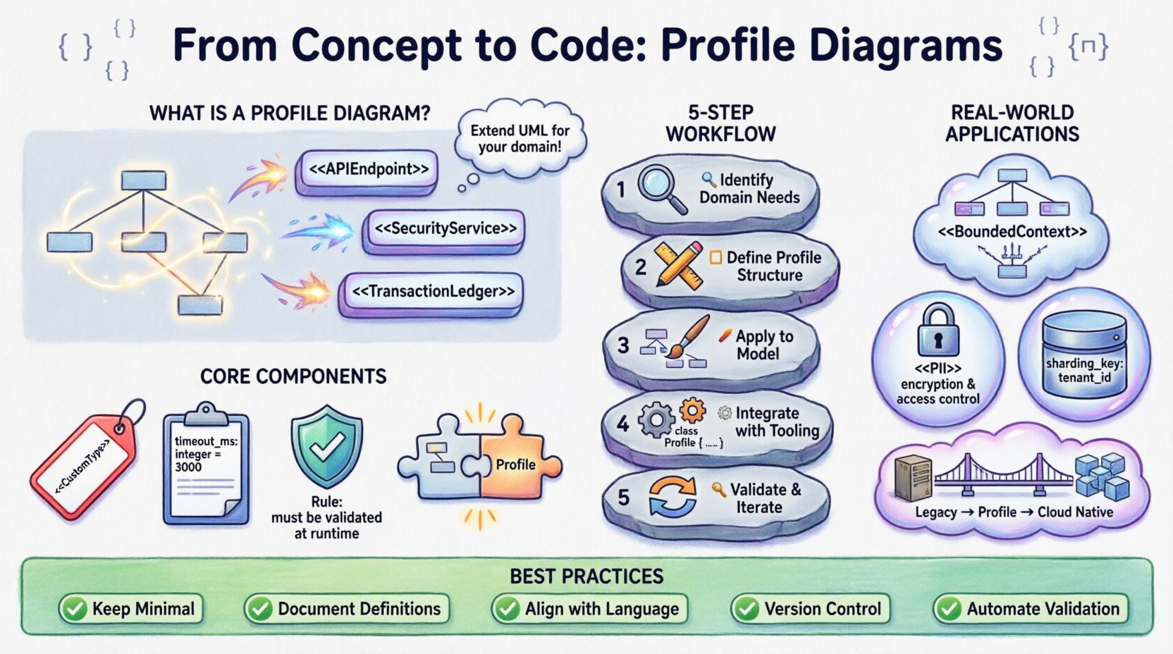
🧩 What is a Profile Diagram?
A Profile Diagram is a specialized UML construct designed to extend the metamodel. Unlike a standard Class or Sequence diagram, which visualizes specific instances or interactions, a Profile Diagram defines a new vocabulary. It allows architects to create stereotypes that map standard UML elements to domain-specific concepts.
Consider a standard class representing a database table. In a generic model, this is just a collection of attributes. In a profile for a financial system, that same class might be stereotyped as a TransactionLedger with specific constraints on data integrity and audit trails. The Profile Diagram captures these definitions, ensuring consistency across all diagrams in the project.
Key characteristics include:
- Meta-modeling: It operates one level above the standard model, defining rules for how other elements should be treated.
- Extensibility: It adds new keywords and attributes without changing the core UML specification.
- Contextualization: It aligns the model with the business domain, reducing ambiguity between developers and stakeholders.
🛠️ Core Components of a Profile
To build an effective profile, you must understand its building blocks. These components allow you to attach metadata to standard modeling elements. Think of them as annotations that carry specific meaning within your environment.
| Component | Description | Use Case Example |
|---|---|---|
| Stereotypes | New keywords that classify model elements. | Marking a class as < |
| Tagged Values | Custom properties that hold specific data. | Adding a property timeout_ms to a component. |
| Constraints | Logical rules that elements must satisfy. | Ensuring a < |
| Dependencies | Links between the profile and the metamodel. | Defining which standard UML classes the profile extends. |
🔄 The Workflow: From Concept to Implementation
Integrating a profile into a project requires a structured approach. Rushing into diagramming without defining the vocabulary first often leads to inconsistent models. Follow this logical progression to ensure your profiles add value.
1. Identify Domain Needs
Start by analyzing the gaps in your current modeling language. Where do stakeholders use different terms for the same concept? Where does the code require specific metadata that the standard model ignores? For example, in a cloud-native architecture, you might need to distinguish between stateless and stateful services explicitly in the design phase.
2. Define the Profile Structure
Once needs are identified, draft the profile. Create new stereotypes for your key concepts. Define the tagged values that accompany them. Ensure that the constraints are enforceable. This step is purely about the rules of the game, not the specific game pieces.
3. Apply to the Model
With the profile defined, apply it to your actual diagrams. Instead of drawing generic boxes, use your new stereotypes. This forces the team to think about the specific properties of each element. A component labeled <
4. Integrate with Tooling
Configure your modeling environment to recognize the profile. This often involves loading a specific extension file or setting up a template. Ensure that code generators or documentation tools are configured to read these tags. If the profile exists in the diagram but is ignored by the build pipeline, it becomes technical debt.
5. Validate and Iterate
Profiles are not static. As the project evolves, so do the requirements. Review the profile periodically. Are the stereotypes still relevant? Are there new constraints needed? Remove unused elements to keep the model clean.
🌍 Real-World Application Scenarios
The utility of Profile Diagrams becomes clear when applied to specific architectural challenges. Below are common scenarios where these diagrams provide significant clarity.
- Microservices Architecture: Defining boundaries between services using stereotypes like <
> or < >. This helps visualize data ownership and communication protocols without cluttering the diagram with network topology details. - Security Compliance: In regulated industries, data classification is vital. A profile can enforce that any class marked <
> must have specific encryption attributes and audit logging constraints defined in the model. - Database Abstraction: When supporting multiple database backends, a profile can abstract the storage layer. Instead of detailing specific SQL schemas, developers model logical entities with tags indicating replication strategies or sharding keys.
- Legacy Migration: When modernizing older systems, a profile can map old concepts to new ones. This creates a bridge diagram that documents the transformation logic, aiding in the gradual replacement of functionality.
🔗 Code Integration and Generation
The true power of a Profile Diagram lies in its ability to influence the generated code. When models are used for Model-Driven Development (MDD), the profile acts as the instruction set for the generator.
Here is how the integration typically functions:
- Annotation Generation: Code generators can translate tagged values into language-specific annotations. For instance, a
timeout_mstag in the model might become a@Timeoutannotation in Java or atimeout:directive in C#. - Validation Logic: Constraints defined in the profile can be compiled into runtime checks or static analysis rules. If a profile specifies that a <
> must not access a < > directly, the build process can flag violations before deployment. - Documentation: Profiles provide context for API documentation. Swagger or OpenAPI definitions can be enriched with profile metadata, providing developers with more than just endpoint signatures.
It is crucial to maintain a bidirectional flow. Changes in code should ideally reflect back in the model. If a developer modifies the implementation significantly, the profile constraints should be re-evaluated to ensure the model remains accurate.
⚠️ Common Pitfalls and Challenges
While powerful, Profile Diagrams can introduce complexity if not managed correctly. Teams often fall into traps that reduce productivity rather than enhancing it.
| Pitfall | Impact | Mitigation Strategy |
|---|---|---|
| Over-Engineering | Creating profiles for every minor concept makes the model heavy and slow. | Limit profiles to high-level architectural concerns. Keep them simple. |
| Tool Fragmentation | Different tools interpret profiles differently, breaking compatibility. | Standardize on a single modeling platform or use open standards like XMI. |
| Lack of Maintenance | Profiles become outdated as the system evolves, leading to confusion. | Assign ownership of the profile to a specific architect or team lead. |
| Stakeholder Disconnect | Developers understand the profile, but business stakeholders do not. | Document the profile definitions in plain language alongside the diagrams. |
✅ Best Practices for Implementation
To ensure your Profile Diagrams remain a helpful asset, adhere to these guidelines.
- Keep it Minimal: Start with a small set of stereotypes. Add more only when a pattern repeats consistently. If you find yourself creating a new stereotype for every class, reconsider the abstraction level.
- Document Definitions: Every stereotype should have a clear definition. What does it mean for a class to be <
>? Is it a code guarantee or a design intent? Write this down. - Align with Language: Ensure your profile names match the programming language conventions where possible. Using <
> is clearer than < > if your codebase uses handlers. - Version Control: Treat profile definitions as code. Store them in your version control system. This allows you to track changes to the modeling language itself.
- Automate Validation: Where possible, use scripts to validate that models adhere to the profile constraints. This reduces manual review time.
📉 Managing Profile Lifecycle
A profile is a living document. It requires the same lifecycle management as the software it describes. When a new technology is adopted, the profile may need updates. When a legacy component is retired, its stereotypes may become obsolete.
Regular audits are necessary. Schedule reviews at the end of major sprints or release cycles. Ask the team: “Does this stereotype help us make better decisions?” If the answer is no, consider removing it.
Communication is key. When updating a profile, notify all stakeholders. A change in a stereotype definition can ripple through existing diagrams. Clear changelogs prevent confusion during refactoring efforts.
🎯 Final Thoughts on Modeling Strategy
Using Profile Diagrams effectively requires a balance between abstraction and specificity. They are not a silver bullet, but a tool for precision. When implemented correctly, they reduce the cognitive load on developers by making implicit assumptions explicit.
The goal is not to create more diagrams, but to make the existing ones more meaningful. By extending the standard vocabulary to fit your specific domain, you create a shared understanding that spans from the initial design to the final deployment. This alignment minimizes errors, accelerates onboarding for new team members, and ensures that the architecture remains consistent as the system scales.
Focus on the value the profile brings to the development process. If it clarifies a complex relationship or enforces a critical constraint, it is worth the effort. If it adds noise without adding insight, it is time to simplify.
Adopting this approach transforms modeling from a bureaucratic exercise into a strategic advantage. It allows your team to speak a language that is uniquely suited to the problems you are solving, ensuring that the code reflects the intent of the design accurately and reliably.