
Designing architecture for systems that grow requires more than just drawing boxes and lines. It demands a structured approach to visual communication. Profile diagrams serve as a critical component in modeling complex environments. They allow teams to define custom stereotypes and extend standard notation to fit specific domain needs. When dealing with large-scale systems, clarity becomes a scarce resource. The goal is to produce diagrams that remain readable as complexity increases. This guide explores the strategies required to build diagrams that scale alongside the software they represent.
📐 Understanding Profile Diagrams in Modern Context
A profile diagram acts as a blueprint for notation. It defines how standard elements are interpreted within a specific context. In large organizations, different teams often speak different technical languages. A profile diagram bridges these gaps by standardizing terminology. It ensures that when one architect draws a component, another understands its behavior and constraints. This standardization is vital when the system spans multiple departments or geographic locations.
Without a defined profile, diagrams become subjective. One developer might interpret a connector as a synchronous call, while another sees a message queue. Profiles resolve this ambiguity. They attach metadata to elements, providing context that standard shapes cannot convey. This metadata includes properties, tags, and extended relationships.
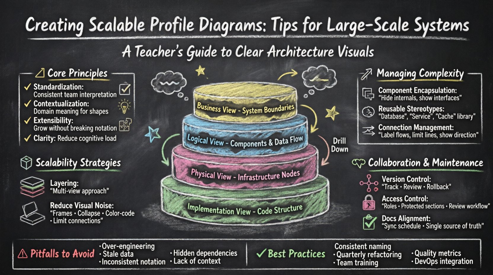
- Standardization: Ensures consistent interpretation across teams.
- Contextualization: Adds domain-specific meaning to generic shapes.
- Extensibility: Allows the model to grow without breaking existing notation.
- Clarity: Reduces cognitive load for stakeholders reviewing the architecture.
When scaling, the volume of information increases exponentially. A profile diagram helps manage this volume by abstracting low-level details. It allows architects to focus on high-level interactions without getting lost in implementation specifics. This abstraction is the key to maintaining a diagram that remains useful over time.
🧱 Planning for Scalability and Structure
Scalability in diagramming begins before the first shape is placed. It involves planning how information will be grouped and presented. Large-scale systems often require multiple views. A single diagram cannot show every detail without becoming unreadable. Therefore, the strategy must involve layering information.
1. Layering and Abstraction
Think of the diagram as a multi-layered cake. Each layer reveals more detail than the one before. The top layer shows business capabilities. The middle layer shows logical components. The bottom layer shows physical deployment. This separation prevents information overload.
- High-Level View: Focus on system boundaries and external interfaces.
- Logical View: Detail internal components and data flow.
- Physical View: Map components to infrastructure nodes.
- Implementation View: Show code structure and dependencies.
By organizing content into these layers, you create a navigation path for the reader. They can drill down into specific areas only when necessary. This keeps the initial view clean and focused.
2. Managing Visual Noise
As systems grow, so does the number of connections. Too many lines create a “spaghetti” effect. This visual noise obscures the actual architecture. To combat this, use grouping techniques effectively.
- Use Frames: Group related components into distinct areas.
- Hide Details: Collapse complex subsystems into single blocks.
- Limit Connections: Only draw lines that represent critical data paths.
- Color Coding: Use distinct colors for different system domains.
Visual noise is the enemy of scalability. If a stakeholder cannot find the critical path within ten seconds, the diagram has failed. Stripping away non-essential lines is a deliberate act of editing, not a limitation of the tool.
🔗 Managing Complexity and Modularity
Complexity in large systems is inevitable. It stems from the number of interacting parts. The profile diagram must reflect this complexity without confusing the audience. Modularity is the solution. Just as code is modular, diagrams should be too.
1. Component Encapsulation
Encapsulation means hiding internal complexity behind a defined interface. In a diagram, this looks like a box with a clear border. Inside, the details exist, but they are not the focus of the current view. This allows the system to evolve internally without requiring changes to the external diagram.
- Define Interfaces: Clearly mark input and output points.
- Seal Boundaries: Do not draw lines crossing module boundaries unless necessary.
- Internalize Logic: Keep implementation logic inside the component box.
2. Reusable Stereotypes
Profiles rely on stereotypes. These are custom tags applied to standard elements. For example, a standard box can become a “Database” or a “Service” through a stereotype. When building large systems, create a library of these stereotypes.
Pre-defined stereotypes ensure consistency. If every developer uses the same tag for a “Cache,” the diagram becomes self-documenting. This reduces the need for legends and notes. It speeds up the review process significantly.
- Create a Library: Store common stereotypes for team access.
- Document Definitions: Explain what each stereotype implies.
- Enforce Usage: Require teams to use approved stereotypes only.
3. Connection Management
Connections represent dependencies. In large systems, dependencies can be dense. Managing them requires discipline. Avoid drawing every single dependency. Focus on the ones that affect system behavior.
- Group Flows: Combine multiple similar data streams into one line.
- Label Clearly: Every line must have a description of the data type.
- Directionality: Ensure arrows point in the correct direction of control.
🤝 Collaboration and Maintenance
Diagrams are living documents. They must be maintained as the system changes. In large teams, collaboration is key. Multiple people may need to edit the model simultaneously or sequentially. Without a maintenance strategy, diagrams become outdated quickly.
1. Version Control Integration
Just like code, diagrams should be versioned. This allows teams to track changes over time. It provides an audit trail for architectural decisions. If a system is refactored, the diagram history shows the evolution of the structure.
- Track Changes: Record who made the change and when.
- Review History: Compare versions to understand architectural shifts.
- Rollback Capability: Ability to revert to a previous state if needed.
2. Access Control and Permissions
Not every team member needs to edit every part of the diagram. Large models require access control. This prevents accidental changes to critical architecture sections.
- Role-Based Access: Define who can view, edit, or comment.
- Protected Sections: Lock core infrastructure diagrams from modification.
- Review Workflow: Require approval before merging diagram changes.
3. Documentation Alignment
Diagrams should not exist in a vacuum. They must align with written documentation. If the text says one thing and the diagram says another, trust is lost. Regular audits ensure alignment.
- Sync Schedule: Set a routine to check consistency.
- Single Source of Truth: Decide which document leads the definition.
- Update Triggers: Update diagrams when code or infrastructure changes.
🚫 Common Pitfalls to Avoid
Even experienced architects make mistakes when scaling diagrams. Recognizing these pitfalls helps prevent them. Below are common issues and how to address them.
| Pitfall | Impact | Mitigation Strategy |
|---|---|---|
| Over-Engineering | Diagram becomes too complex to read. | Focus on the “why” rather than the “how”. |
| Stale Data | Misleads developers during implementation. | Integrate diagram updates into deployment pipelines. |
| Inconsistent Notation | Causes confusion between teams. | Enforce a strict style guide and profile library. |
| Hidden Dependencies | Breaks systems during refactoring. | Map all critical data flows explicitly. |
| Lack of Context | Readers do not understand the scope. | Include a legend and system boundary definition. |
🛠️ Best Practices for Long-Term Viability
To ensure the diagrams remain useful years down the line, specific habits must be adopted. These practices focus on longevity and adaptability.
1. Consistent Naming Conventions
Naming is the foundation of clarity. Every element, line, and group should follow a strict naming convention. This reduces ambiguity and improves searchability within the model.
- Prefixed Names: Use prefixes to denote domain (e.g.,
APP-User,SVC-Auth). - Lowercase Separators: Use underscores or hyphens consistently.
- Avoid Abbreviations: Use full words unless standard industry terms are used.
2. Regular Refactoring
Just like code, diagrams get “dirty.” They accumulate unnecessary elements. Schedule regular refactoring sessions to clean up the model. Remove unused components and consolidate redundant groups.
- Quarterly Reviews: Schedule time to audit the model.
- Remove Dead Code: Delete elements that no longer exist in production.
- Simplify Structures: Merge overly complex groups into simpler views.
3. Training and Onboarding
New team members need to understand the diagram standards. Training ensures everyone contributes to the model correctly. This reduces errors and improves the overall quality of the architecture documentation.
- Style Guides: Create a document outlining the rules.
- Workshops: Conduct sessions on how to use the profile tools.
- Mentorship: Pair junior architects with seniors for review.
🔍 Evaluating Diagram Quality
How do you know if a profile diagram is successful? Use specific metrics to evaluate quality. These metrics focus on readability and utility.
- Readability Score: Can a new developer understand the flow in 5 minutes?
- Accuracy Rate: Does the diagram match the running system?
- Update Frequency: How often is the diagram updated after changes?
- Stakeholder Satisfaction: Do managers and developers find it useful?
🌐 Integrating with DevOps
Modern systems are built using automation. Diagrams should fit into this workflow. Manual updates are prone to error. Integrating diagram generation or validation into the CI/CD pipeline ensures accuracy.
- Automated Extraction: Pull data from code repositories to update diagrams.
- Validation Scripts: Check for missing dependencies or broken links.
- Notification Systems: Alert teams when diagrams drift from reality.
This integration reduces the maintenance burden. It shifts the focus from drawing to verifying. It ensures the diagram remains a reliable source of truth without constant manual intervention.
📈 The Future of System Modeling
The field of system modeling continues to evolve. New standards are emerging that focus on interoperability and automation. Staying informed about these changes helps teams remain competitive. However, the core principles of clarity and structure remain constant.
Large-scale systems will only grow more complex. The diagrams used to describe them must be robust enough to handle this growth. By following the strategies outlined in this guide, teams can create models that stand the test of time. The investment in high-quality diagrams pays dividends in reduced errors and faster onboarding.
Remember, the diagram is a communication tool. Its success is measured by how well it conveys information to the intended audience. Prioritize the reader over the drawer. Keep the design simple, the notation consistent, and the maintenance regular. These habits build a foundation for sustainable architecture documentation.