
Creating a robust system architecture relies heavily on clear communication and standardized modeling. Within the Unified Modeling Language (UML) ecosystem, the Profile Diagram serves as a critical mechanism for extending the language itself. It allows architects to tailor the modeling syntax to specific domains, ensuring that diagrams accurately reflect business logic and technical constraints. Without a well-defined profile, models can become ambiguous, leading to misinterpretations during development and deployment phases.
This guide explores the essential practices for constructing effective Profile Diagrams. We will examine the structural components, naming conventions, and maintenance strategies that ensure long-term usability. By adhering to these standards, solution architects can create models that are both precise and adaptable to changing requirements.
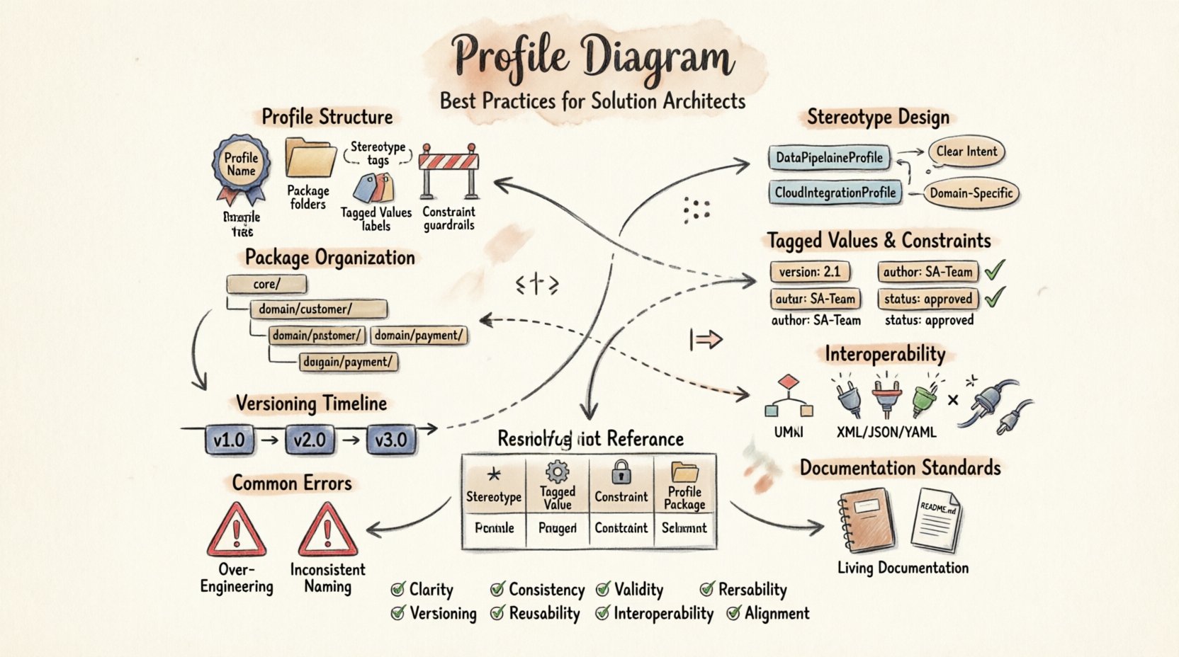
Understanding the Profile Diagram Structure 🔍
A Profile Diagram is not a standalone artifact but an extension of the core UML metamodel. It defines new elements that can be applied to existing classes, components, or relationships. Think of it as a dictionary that adds specific terms to the language used in your architecture. To build a reliable profile, one must understand the foundational elements that make it function.
- Profile Name: A unique identifier for the extension package.
- Package Structure: Organizes stereotypes and metadata into logical groups.
- Stereotypes: The primary building blocks that add new semantics to model elements.
- Tagged Values: Custom properties that allow for additional data storage on elements.
- Constraints: Rules that define valid states or relationships for the extended elements.
When designing the structure, architects should avoid creating overly deep hierarchies. A flat structure is often easier to navigate and maintain than a deeply nested one. This simplicity reduces cognitive load for team members who must interpret the diagrams later in the project lifecycle.
Designing Stereotypes with Precision 🏷️
Stereotypes are the most visible part of a Profile Diagram. They modify the appearance and meaning of standard UML elements. A well-designed stereotype clearly indicates its purpose without requiring extensive external documentation. The naming convention is the first step in ensuring clarity.
Naming Conventions
Names should be descriptive and consistent. Avoid generic terms like Entity or Service unless they are universally understood within the specific domain. Instead, use domain-specific terminology that conveys exact meaning.
- Use PascalCase: Start names with a capital letter for consistency.
- Limit Length: Keep names concise to prevent clutter in diagrams.
- Avoid Ambiguity: Ensure names do not conflict with standard UML keywords.
- Contextual Relevance: Include context in the name if the stereotype applies to a specific subsystem.
For example, instead of using <<Component>> for every class, a specific profile might define <<Gateway>> or <<Repository>>. This distinction helps developers immediately understand the architectural pattern intended for that element.
Semantic Clarity
Every stereotype must have a clear definition. This definition should explain not just what the element is, but how it behaves within the system. Documentation should accompany each stereotype in the model repository.
- Define Purpose: State the architectural role clearly.
- Specify Constraints: List any rules that must be followed.
- Provide Examples: Show how the stereotype is applied in practice.
Clarity in semantics prevents the model from becoming a static drawing. It becomes a living specification that guides implementation.
Managing Tagged Values and Constraints 📏
Tagged values extend the data capacity of model elements. They allow architects to store metadata directly on the diagram, such as version numbers, priority levels, or ownership details. However, the power of tagged values comes with the responsibility of management.
Defining Tagged Values
Do not create a tagged value for every possible piece of information. This leads to data pollution and makes diagrams difficult to read. Only define values that are critical for the architecture or downstream processes.
- Essential Data: Include values required for code generation or deployment scripts.
- Traceability: Use values to link models to requirements or test cases.
- Standardization: Ensure data types are consistent (e.g., all dates use ISO 8601 format).
Applying Constraints
Constraints enforce business rules within the model. They act as guardrails that prevent invalid configurations. Constraints can be expressed using OCL (Object Constraint Language) or plain text, depending on the tooling capabilities.
- Validation: Use constraints to validate data integrity before implementation.
- Dependency Rules: Define which elements can or cannot coexist.
- Lifecycle States: Specify valid transitions between system states.
When applying constraints, ensure they are testable. If a constraint cannot be verified, it serves no purpose in the modeling process.
Namespace and Package Organization 📂
Profiles often grow over time as new requirements emerge. Without a logical organization strategy, the profile can become a tangled web of dependencies. Namespace management is crucial for maintaining order.
Logical Grouping
Group stereotypes and extensions by domain or subsystem. This separation allows teams to work on specific areas without affecting others. It also simplifies the import process when sharing profiles across projects.
- Domain Separation: Keep business logic separate from technical infrastructure.
- Subsystem Grouping: Organize by functional modules or layers.
- Version Isolation: Store different versions of a profile in distinct packages.
Import Mechanisms
Profiles should be reusable. This means they must be designed to be imported into other models without conflict. Avoid hard-coding dependencies on specific packages. Use relative paths or standardized namespaces to ensure portability.
- External References: Reference standard UML elements by their canonical names.
- Dependency Minimization: Reduce reliance on external packages to prevent breakage.
- Modularity: Split large profiles into smaller, manageable modules.
Ensuring Interoperability Across Platforms 🔄
One of the primary goals of modeling is to facilitate communication between different stakeholders and tools. A Profile Diagram must be compatible with the tools used by developers, testers, and operations teams.
Tool Agnosticism
Design profiles that work across multiple modeling platforms. Avoid proprietary features that lock the model into a single vendor environment. This ensures that the architecture remains accessible even if the software stack changes.
- Standard Syntax: Use standard UML syntax wherever possible.
- Export Formats: Ensure models can be exported to XMI or other open formats.
- Metadata Portability: Verify that tagged values transfer correctly between tools.
Documentation for Consumers
Interoperability also depends on understanding. Provide clear documentation for anyone who needs to use the profile. This includes developers who generate code from the model and testers who use it for validation.
- Readme Files: Include a text file explaining the profile’s purpose.
- Usage Guides: Create step-by-step instructions for applying stereotypes.
- FAQs: Address common questions about specific elements.
Lifecycle Management and Versioning 🔄
Profiles are not static; they evolve as the system and its requirements change. A versioning strategy ensures that changes are tracked and backward compatibility is maintained.
Version Control
Implement a clear versioning scheme for profiles. This helps teams identify which version of the profile is active in a specific project. It also allows for the migration of older models to new standards.
- Semantic Versioning: Use major, minor, and patch numbers to indicate change levels.
- Release Notes: Document what changed between versions.
- Deprecation Policy: Define how old stereotypes are handled in new versions.
Change Management
Changes to a profile should go through a review process. Uncontrolled modifications can break existing models and confuse team members.
- Review Board: Establish a group responsible for approving profile changes.
- Impact Analysis: Assess how changes affect current projects.
- Communication: Notify all stakeholders of updates and their implications.
Common Modeling Errors to Avoid ⚠️
Even experienced architects can make mistakes when designing profiles. Recognizing these pitfalls early can save significant time and effort during the development phase.
Over-Engineering
Do not create a profile for every minor variation. This creates unnecessary complexity. Focus on the core abstractions that truly differentiate your architecture.
- Identify Core Needs: Determine which extensions add real value.
- Reuse Standard Elements: Use existing UML elements before creating new ones.
- Keep it Simple: Aim for the simplest solution that meets requirements.
Inconsistent Application
Ensure that stereotypes are applied consistently across all diagrams. Inconsistency leads to confusion and makes the model unreliable.
- Style Guides: Create a document outlining application rules.
- Automated Checks: Use tools to validate consistency where possible.
- Training: Ensure all team members understand the standards.
Documentation Standards for Profiles 📖
A profile without documentation is a liability. It becomes a black box that only the original designer understands. Proper documentation ensures continuity and knowledge transfer.
Internal Documentation
Embed documentation within the model itself. This ensures that the information travels with the diagram. Most modeling tools allow for notes or descriptions attached to each element.
- Stereotype Descriptions: Explain the meaning of each stereotype.
- Tagged Value Definitions: Define the purpose of each custom property.
- Constraint Explanations: Detail the logic behind validation rules.
External Documentation
Maintain a separate knowledge base for broader context. This repository should contain high-level architecture decisions and strategic guidelines.
- Architecture Decision Records: Document why specific profile choices were made.
- Best Practice Guides: Share lessons learned from previous projects.
- Case Studies: Provide examples of successful profile implementations.
Profile Elements Comparison
To better understand the components of a Profile Diagram, consider the following breakdown of elements and their functions.
| Element | Function | Usage Example |
|---|---|---|
| Stereotype | Extends UML element semantics | <<API>> applied to a Class |
| Tagged Value | Stores metadata on elements | Author: Jane Doe |
| Constraint | Enforces rules on elements | Method must return Boolean |
| Profile Package | Groups related extensions | Namespace: Finance |
Review Checklist for Solution Architects
Before finalizing a Profile Diagram, use this checklist to ensure quality and compliance.
- Clarity: Are all stereotypes clearly named and documented?
- Consistency: Are naming conventions followed throughout the model?
- Validity: Do all constraints pass validation checks?
- Portability: Can the profile be imported into other models?
- Versioning: Is the version number current and recorded?
- Reusability: Is the profile modular and easy to adopt?
- Interoperability: Does it work with standard modeling tools?
- Alignment: Does it match the overall system architecture strategy?
Future Proofing Your Models
The technology landscape evolves rapidly. Profiles designed today must accommodate future changes. This requires a forward-thinking approach to modeling.
Anticipating Change
Design profiles that are flexible enough to handle new requirements without major overhauls. Avoid hard-coding specific technologies or vendors.
- Abstraction: Model at the logical level rather than physical implementation.
- Extensibility: Build profiles that allow for easy addition of new stereotypes.
- Decoupling: Separate business rules from technical implementation details.
Community Engagement
Share your profiles with the broader community. Feedback from other architects can reveal edge cases and improve the robustness of your designs.
- Open Standards: Contribute to industry-wide modeling standards.
- Collaboration: Work with peers to refine common patterns.
- Publication: Publish findings in technical forums or journals.
Conclusion
A well-crafted Profile Diagram is a cornerstone of effective solution architecture. It bridges the gap between abstract requirements and concrete implementation. By following these best practices, architects can create models that are clear, consistent, and maintainable. The investment in proper profile design pays dividends in reduced errors, faster development, and better system quality.
Remember that modeling is a discipline that requires continuous refinement. Stay updated with new standards and adapt your profiles to meet the needs of your specific domain. With careful planning and adherence to these guidelines, your architecture will stand the test of time.