
Modernizing technology stacks is rarely a simple task. When organizations grapple with aging infrastructure, the complexity often lies not just in the code itself, but in the hidden relationships between components. Legacy systems accumulate technical debt over years, resulting in tangled dependencies and opaque architectures. To navigate this landscape effectively, architects need a way to visualize the internal structure of system classifiers. This is where the Composite Structure Diagram (CSD) becomes an essential tool in the system architecture toolkit.
This guide provides a comprehensive roadmap for leveraging Composite Structure Diagrams to analyze, understand, and transform legacy environments. By mapping the internal parts, roles, and ports of your existing systems, you can create a clear path forward. The focus here is on structural clarity, reducing coupling, and establishing a foundation for sustainable evolution.
Understanding the Composite Structure Diagram 🧩
A Composite Structure Diagram is a type of UML (Unified Modeling Language) diagram. It describes the internal structure of a classifier. While standard Class Diagrams show external relationships and attributes, CSDs dive deeper. They reveal what a class or component is made of and how those internal parts interact.
In the context of legacy transformation, a CSD acts as a map of the internal machinery. It breaks down a black box into its constituent elements. This level of granularity is critical when dealing with monolithic applications where the boundary between logical layers is blurred.
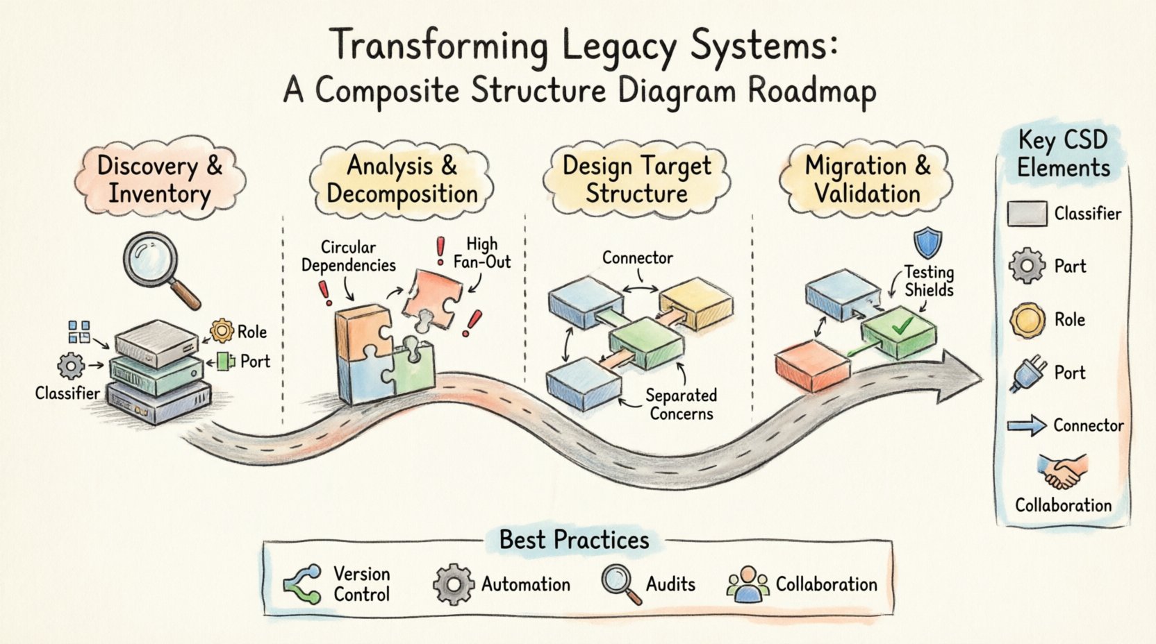
Key Elements in a Composite Structure Diagram
- Classifier: The top-level component being analyzed (e.g., a legacy module or subsystem).
- Part: The internal components that make up the classifier. These represent specific functional units.
- Role: The specific function a part plays within the composite structure.
- Port: The point of interaction where a part connects to the outside world or other parts.
- Connector: The link between ports, defining the flow of data or control.
- Collaboration: The interface or contract defined by the interaction of parts.
When applied to legacy systems, these elements translate directly into physical or logical assets. A Part might be a database table, a specific library, or a microservice. A Connector represents an API call, a message queue, or a direct database join.
Why Use CSDs for Legacy Transformation? 🛠️
Standard documentation often falls short when systems have been in place for over a decade. Code comments may be outdated, and high-level diagrams might hide the complexity that causes failures. A Composite Structure Diagram offers specific advantages for this scenario.
1. Revealing Hidden Coupling
Legacy code often suffers from tight coupling. Modules depend on each other in ways that are not immediately obvious. By defining the internal parts and their connectors, you expose these dependencies. You can see exactly which part relies on which other part, allowing you to target specific areas for decoupling.
2. Clarifying Boundaries
Refactoring requires clear boundaries. Without a CSD, it is easy to accidentally break functionality when moving code. The diagram defines the interface of the composite unit. It shows what must remain stable and what is free to change internally. This is vital for incremental migration strategies.
3. Facilitating Communication
Architects, developers, and business stakeholders often speak different languages. A visual representation of the internal structure bridges this gap. It allows technical teams to explain how a specific feature is implemented without diving into raw code. It also helps stakeholders understand why a change in one area impacts another.
Phase 1: Discovery and Inventory 📋
The first step in any transformation is understanding the current state. This phase is about gathering data and representing it structurally. Do not rush this step. A poor understanding of the legacy state leads to failed migrations.
Step 1.1: Identify the Classifiers
Start by listing the major components of your system. These are the classifiers you will model. In a legacy context, these might be:
- Core business logic modules.
- Legacy databases or data warehouses.
- External integrations and third-party services.
- Authentication and security layers.
For each classifier, create a container in your diagram. This container represents the “Black Box” of the legacy system before you open it up.
Step 1.2: Map the Internal Parts
Inside each classifier container, identify the parts. These are the building blocks. Look for:
- Reusable libraries or frameworks.
- Configuration files that drive behavior.
- Specific algorithms or processing units.
- State management components.
Label each part clearly. Avoid generic names like “Module A”. Use descriptive names that reflect their function, such as “Payment Processing Engine” or “User Session Manager”. This clarity is essential for future maintenance.
Step 1.3: Document the Ports
Ports are the touchpoints. For every part, identify how it communicates. Does it expose an API? Does it read from a file? Does it send an email? List these interactions explicitly. In legacy systems, ports are often undocumented. Dedicate time to reverse-engineer these interfaces by analyzing network traffic or database logs.
Phase 2: Analysis and Decomposition 🔍
Once the structure is mapped, the analysis begins. This is where you identify technical debt and structural anti-patterns. The goal is to find the friction points that prevent modernization.
Step 2.1: Analyze Connectivity
Examine the connectors between parts. Look for:
- Circular Dependencies: Part A calls Part B, which calls Part A. This creates a deadlock risk.
- High Fan-Out: One part connects to too many other parts. This makes changes risky.
- Hardcoded Connections: Direct references to specific database schemas or IP addresses.
Highlight these issues on the diagram. Use visual cues to mark high-risk connections. This visual data drives the prioritization of your refactoring efforts.
Step 2.2: Define Interfaces and Contracts
Legacy systems often rely on implicit contracts. The CSD helps make these explicit. Define what data enters and leaves each port. Specify the data types and the expected format. This definition is crucial when planning to replace a legacy component with a modern alternative.
Consider creating a table to summarize the interface analysis for clarity:
| Component | Port Name | Input Data | Output Data | Complexity Level |
|---|---|---|---|---|
| Order Service | SubmitOrder | JSON Payload | Order ID | High |
| Inventory DB | QueryStock | SKU List | Stock Count | Medium |
| Notification | SendAlert | Event Object | Success Status | Low |
Step 2.3: Identify Replacement Candidates
Not every part needs to be rewritten. Some may be stable and functional. Use the diagram to identify which parts are candidates for replacement. Look for parts that are:
- Technologically obsolete.
- Hard to maintain due to lack of documentation.
- Responsible for the majority of performance bottlenecks.
Conversely, identify parts that should remain. If a core calculation engine is robust but undocumented, it might be better to encapsulate it rather than rewrite it.
Phase 3: Designing the Target Structure 🏗️
With the current state understood, you can design the future state. The Composite Structure Diagram is not just for analysis; it is a design tool for the new architecture.
Step 3.1: Apply Separation of Concerns
Redesign the internal parts to ensure clear separation. In the legacy diagram, you may find logic mixed with data access. In the target diagram, separate these into distinct parts. For example, split a “Service” part into a “Logic” part and a “Persistence” part.
Step 3.2: Standardize Communication
Update the connectors to use modern standards. Replace direct socket connections with message queues. Replace file I/O with API calls. Ensure that the new connectors are loosely coupled. This means the parts should not know the physical location of the parts they connect to.
Step 3.3: Define New Roles
Assign new roles to your parts. A part that used to handle both input and output might be split into an “Input Handler” and an “Output Handler”. This specialization makes the system more resilient. If one role fails, the other can continue to function.
When planning the target structure, consider the following checklist:
- Are all external ports clearly defined?
- Are internal parts reusable across different classifiers?
- Is there a clear path for data flow?
- Are there single points of failure?
Phase 4: Migration and Validation 🚀
The transition from the legacy diagram to the new architecture is the execution phase. This requires careful coordination and validation against the diagrams created in previous phases.
Step 4.1: Incremental Replacement
Do not attempt a “Big Bang” migration. Use the CSD to guide incremental changes. Replace one part at a time. Ensure the new part adheres to the same interface defined in the legacy diagram. This allows the rest of the system to continue functioning without modification.
Step 4.2: Regression Testing
Every time a part is replaced, run the full test suite. The diagram helps you understand the scope of impact. If you change a part in the center of the diagram, check all connectors radiating from it. Validate that the data passing through the connectors remains consistent.
Step 4.3: Documentation Updates
As the system changes, update the diagrams. A static diagram becomes a liability. The CSD should be treated as living documentation. Ensure that the version of the diagram matches the deployed code. This prevents future developers from relying on outdated structural information.
Common Pitfalls in Legacy Modeling ⚠️
Even with a solid plan, challenges arise. Being aware of common mistakes can save significant time and effort.
1. Over-Modeling
Trying to model every single line of code is a trap. A Composite Structure Diagram is meant for high-level structural understanding. Focus on the major parts and their interactions. If a part is too small to impact the architecture, it does not need to be a distinct node in the diagram.
2. Ignoring Non-Functional Requirements
Structural diagrams often focus on functionality. However, legacy transformation must also consider performance and security. When drawing connectors, note if they introduce latency. When defining ports, note if they require encryption. These attributes should be annotated on the diagram.
3. Lack of Stakeholder Buy-in
Technical teams may build the diagram, but business leaders need to understand it. If the diagram does not align with business processes, the transformation will lack support. Ensure the terminology used in the diagram matches the business vocabulary.
Best Practices for Sustainable Architecture 🌱
To ensure the transformation lasts, adopt practices that support long-term health.
- Version Control Diagrams: Treat diagrams as code. Store them in the same repository as the application. This ensures they are reviewed and updated during the development lifecycle.
- Automate Generation: Where possible, generate diagrams from code. This keeps the visual representation in sync with the actual implementation.
- Regular Audits: Schedule periodic reviews of the structure. As the system evolves, the structure may drift. Regular audits catch this drift early.
- Collaborative Modeling: Do not let one architect draw the whole system. Involve developers who know the specific parts. This ensures accuracy and shared ownership.
Conclusion on Structural Clarity 📝
Transforming legacy systems is a complex journey that requires precision and foresight. The Composite Structure Diagram provides the necessary lens to see inside the black box. It turns abstract code into a tangible map of parts, roles, and connections.
By following a structured roadmap, organizations can reduce risk and increase confidence during migration. The process moves from discovery to analysis, then to design and finally to validation. Throughout this journey, the diagram serves as the single source of truth.
Remember that the goal is not just to change technology, but to improve maintainability and agility. A well-structured system allows teams to respond to market changes faster. The effort invested in modeling the structure pays dividends in the stability and speed of future development.
Start with the current state. Map the internals. Identify the friction. Design the future. Execute with care. This path leads to a resilient architecture capable of supporting the next generation of business needs.