
A practitioner’s review and hands-on guide to visualizing system requirements through use case modeling
🎯 New Introduction: Why Use Case Diagrams Changed How I Design Software
When I first started in product management, requirements gathering felt like trying to catch smoke with bare hands. Stakeholders would describe features in abstract terms, developers would interpret them differently, and by the time we reached testing, we’d realize we’d built something nobody actually needed.
That changed when I discovered UML use case diagrams—and specifically, when I started using Visual Paradigm to bring them to life.

This guide isn’t just a dry specification reference. It’s the distilled experience of someone who’s used these diagrams to align cross-functional teams, onboard new developers, and communicate complex system boundaries to non-technical stakeholders. Whether you’re a BA, PM, developer, or student, you’ll find practical insights alongside the formal notation definitions.
Let’s dive in.
📐 UML Use Case Diagram Notations: The Visual Vocabulary
 |
|---|
| Sample UML use case diagram |
Use case diagrams are a cornerstone of UML (Unified Modeling Language), and Visual Paradigm makes them accessible without sacrificing precision. Below is the complete notation toolkit I rely on daily:
| Icon | Name |
|---|---|
| Use Case | |
| Association | |
| Actor | |
| System | |
| Include | |
| Extend | |
| Dependency | |
| Generalization | |
| Realization | |
| Collaboration |
| List of UML notations available in UML use case diagram |
|---|
🔍 Deep Dive: Core Notations Explained (With Real-World Context)
Use Case
 |
|---|
| UML use case |
A use case represents a user goal that can be achieved by accessing the system or software application. In Visual Paradigm, you can make use of the sub-diagram feature to describe the interaction between user and system within a use case by creating a sub-sequence diagram under a use case. You can also describe the use case scenario using the Flow of Events editor.
💡 Pro Tip from Experience: I always start with verb-noun naming (“Place Order,” “Generate Report”)—it keeps the focus on user outcomes, not system internals.
OMG UML Specification
What is a use case in UML? According to the OMG Unified Modeling Language (OMG UML) specification (UML Superstructure Specification version 2.4.1, page 606), use case is:
A use case is the specification of a set of actions performed by a system, which yields an observable result that is typically of value for one or more actors or other stakeholders of the system.
Association
 |
|---|
| UML association |
Actor and use case can be associated to indicate that the actor participates in that use case. Therefore, an association correspond to a sequence of actions between the actor and use case in achieving the use case.
OMG UML Specification
What is an association in UML? According to the OMG Unified Modeling Language (OMG UML) specification (UML Superstructure Specification version 2.4.1, page 36), association is:
An association describes a set of tuples whose values refer to typed instances. An instance of an association is called a link. A link is a tuple with one value for each end of the association, where each value is an instance of the type of the end.
…
An association specifies a semantic relationship that can occur between typed instances. It has at least two ends represented by properties, each of which is connected to the type of the end. More than one end of the association may have the same type.
An end property of an association that is owned by an end class or that is a navigable owned end of the association indicates that the association is navigable from the opposite ends; otherwise, the association is not navigable from the opposite ends.
Actor
 |
|---|
| UML actor |
Actors are the entities that interact with a system. Although in most cases, actors are used to represent the users of system, actors can actually be anything that needs to exchange information with the system. So, an actor may be people, computer hardware, other systems, etc.
Note that actor represents a role that a user can play but not a specific user. So, in a hospital information system, you may have doctor and patient as actors but not Dr. John, Mrs. Brown as actors.
💡 Pro Tip from Experience: I’ve seen teams get stuck modeling “John the Admin” as an actor. Remember: model roles, not people. It keeps your diagram scalable and reusable.
OMG UML Specification
What is an actor in UML? According to the OMG Unified Modeling Language (OMG UML) specification (UML Superstructure Specification version 2.4.1), actor is:
An actor specifies a role played by a user or any other system that interacts with the subject. (The term “role” is used informally here and does not necessarily imply the technical definition of that term found elsewhere in this specification.)
…
An Actor models a type of role played by an entity that interacts with the subject (e.g., by exchanging signals and data) but which is external to the subject (i.e. in the sense that an instance of an actor is not a part of the instance of its corresponding subject). Actors may represent roles played by human users, external hardware, or other subjects. Note that an actor does not necessarily represent a specific physical entity but merely a particular facet (i.e.”role”) of some entity that is relevant to the specification of its associated use cases. Thus, a single physical instance may play the role of several different actors and conversely, a given actor may be played by multiple different instances.
System
 |
|---|
| UML system |
The scope of a system can be represented by a system (shape), or sometimes known as a system boundary. The use cases of the system are placed inside the system shape, while the actor who interact with the system are put outside the system. The use cases in the system make up the total requirements of the system.
OMG UML Specification
What is a system in UML? According to the OMG Unified Modeling Language (OMG UML) specification (UML Superstructure Specification version 2.4.1, page 608), system is:
If a subject (or system boundary) is displayed, the use case ellipse is visually located inside the system boundary rectangle. Note that this does not necessarily mean that the subject classifier owns the contained use cases, but merely that the use case applies to that classifier.
Include
 |
|---|
| UML include |
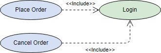
An include relationship specifies how the behavior for the inclusion use case is inserted into the behavior defined for the base use case.
💡 Pro Tip from Experience: Use
<<include>>for mandatory, reusable steps—like “Authenticate User” that appears in dozens of flows. It reduces duplication and keeps diagrams clean.
OMG UML Specification
What is an include in UML? According to the OMG Unified Modeling Language (OMG UML) specification (UML Superstructure Specification version 2.4.1, page 604), include is:
An include relationship defines that a use case contains the behavior defined in another use case.
Extend
 |
|---|
| UML extend |
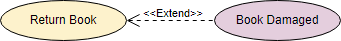
An extend relationship specifies how the behavior of the extension use case can be inserted into the behavior defined for the base use case.
💡 Pro Tip from Experience: Reserve
<<extend>>for optional or conditional behavior—like “Apply Discount Code” during checkout. It clarifies what’s core vs. what’s situational.
OMG UML Specification
What is an extend in UML? According to the OMG Unified Modeling Language (OMG UML) specification (UML Superstructure Specification version 2.4.1, page 601), extend is:
A relationship from an extending use case to an extended use case that specifies how and when the behavior defined in the extending use case can be inserted into the behavior defined in the extended use case.
…
This relationship specifies that the behavior of a use case may be extended by the behavior of another (usually supplementary) use case. The extension takes place at one or more specific extension points defined in the extended use case. Note, however, that the extended use case is defined independently of the extending use case and is meaningful independently of the extending use case. On the other hand, the extending use case typically defines behavior that may not necessarily be meaningful by itself. Instead, the extending use case defines a set of modular behavior increments that augment an execution of the extended use case under specific conditions.
Note that the same extending use case can extend more than one use case. Furthermore, an extending use case may itself be extended.
Dependency
 |
|---|
| UML dependency |
A dependency relationship represents that a model element relies on another model element for specification and/or implementation.
OMG UML Specification
What is a dependency in UML? According to the OMG Unified Modeling Language (OMG UML) specification (UML Superstructure Specification version 2.4.1, page 61), dependency is:
A dependency is a relationship that signifies that a single or a set of model elements requires other model elements for their specification or implementation. This means that the complete semantics of the depending elements is either semantically or structurally dependent on the definition of the supplier element(s).
Generalization
 |
|---|
| UML generalization |
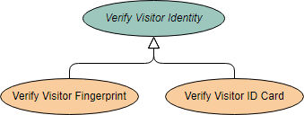
A generalization relationship is used to represent inheritance relationship between model elements of same type. The more specific model element share the same specification with. the more general the model element but carries more details in extra.
OMG UML Specification
What is a generalization in UML? According to the OMG Unified Modeling Language (OMG UML) specification (UML Superstructure Specification version 2.4.1, page 70), generalization is:
A generalization is a taxonomic relationship between a more general classifier and a more specific classifier. Each instance of the specific classifier is also an indirect instance of the general classifier. Thus, the specific classifier inherits the features of the more general classifier.
Realization
 |
|---|
| UML realization |
A realization is a relationship between a specification and its implementation.
OMG UML Specification
What is a realization in UML? According to the OMG Unified Modeling Language (OMG UML) specification (UML Superstructure Specification version 2.4.1, page 131), realization is:
Realization is a specialized abstraction relationship between two sets of model elements, one representing a specification (the supplier) and the other represents an implementation of the latter (the client). Realization can be used to model stepwise refinement, optimizations, transformations, templates, model synthesis, framework composition, etc.
Collaboration
 |
|---|
| UML collaboration |
OMG UML Specification
What is a collaboration in UML? According to the OMG Unified Modeling Language (OMG UML) specification (UML Superstructure Specification version 2.4.1, page 174), collaboration is:
A collaboration describes a structure of collaborating elements (roles), each performing a specialized function, which collectively accomplish some desired functionality. Its primary purpose is to explain how a system works and, therefore, it typically only incorporates those aspects of reality that are deemed relevant to the explanation. Thus, details, such as the identity or precise class of the actual participating instances are suppressed.
🚀 Use Case Diagram Tutorial: From Concept to Clarity
A use case describes how a user uses a system to accomplish a particular goal. A use case diagram consists of the system, the related use cases and actors and relates these to each other to visualize: what is being described? (system), who is using the system? (actors) and what do the actors want to achieve? (use cases), thus, use cases help ensure that the correct system is developed by capturing the requirements from the user’s point of view.
What is a Use Case Diagram in UML?
A use case is a list of actions or event steps typically defining the interactions between a role of an actor and a system to achieve a goal. A use case is a useful technique for identifying, clarifying, and organizing system requirements. A use case is made up of a set of possible sequences of interactions between systems and users that defines the features to be implemented and the resolution of any errors that may be encountered.
While a use case itself might drill into a lot of detail (such as, flow of events and scenarios) about every possibility, a use-case diagram can help provide a higher-level view of the system, providing the simplified and graphical representation of what the system must actually do.
A use case (or set of use cases) has these characteristics:
-
Organizes functional requirements
-
Models the goals of system/actor (user) interactions
-
Describes one main flow of events (main scenarios) and possibly other exceptional flows (alternatives), also called paths or user scenarios
Use Case Diagram Notations
Use cases define interactions between external actors and the system to attain particular goals. A use case diagram contains four main components
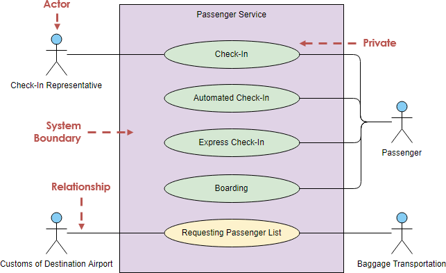
Actor
Actors are usually individuals involved with the system defined according to their roles. The actor can be a human or other external system.
Use Case
A use case describes how actors uses a system to accomplish a particular goal. Use cases are typically initiated by a user to fulfill goals describing the activities and variants involved in attaining the goal.
Relationship
The relationships between and among the actors and the use cases.
System Boundary
The system boundary defines the system of interest in relation to the world around it.
Benefits of Use Case Diagram
-
Use cases is a powerful technique for the elicitation and documentation of black-box functional requirements.
-
Because, use cases are easy to understand and provide an excellent way for communicating with customers and users as they are written in natural language.
-
Use cases can help manage the complexity of large projects by partitioning the problem into major user features (i.e., use cases) and by specifying applications from the users’ perspective.
-
A use case scenario, often represented by a sequence diagram, involves the collaboration of multiple objects and classes, use cases help identify the messages (operations and the information or data required – parameters) that glue the objects and classes together.
-
Use cases provide a good basis to link between the verification of the higher-level models (i.e. interaction between actors and a set of collaborative objects), and subsequently, for the validation of the functional requirements (i.e. blueprint of white-box test).
-
Use case driven approach provides an traceable links for project tracking in which the key development activities such as the use cases implemented, tested, and delivered fulfilling the goals and objectives from the user point of views.
How to Draw a Use Case Diagram?
A Use Case model can be developed by following the steps below.
-
Identify the Actors (role of users) of the system.
-
For each category of users, identify all roles played by the users relevant to the system.
-
Identify what are the users required the system to be performed to achieve these goals.
-
Create use cases for every goal.
-
Structure the use cases.
-
Prioritize, review, estimate and validate the users.
💡 Agile Adaptation: To make the use case approach more “Agile”, do not detail all use cases upfront. Prioritize them in your product backlog and refine use cases at different levels of detail according to the development phase—just-in-time and just-enough.
You can also:
-
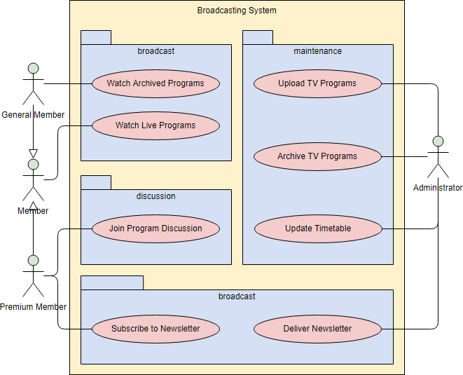
Draw packages for logical categorization of use cases into related subsystems.
Structuring Use Cases
UML defines three stereotypes of association between Use Cases:
<> Use Case
The time to use the <> relationship is after you have completed the first cut description of all your main Use Cases. You can now look at the Use Cases and identify common sequences of user-system interaction.
<> Use Case
An extending use case is, effectively, an alternate course of the base use case. The <> use case accomplishes this by conceptually inserting additional action sequences into the base use-case sequence.
Abstract and Generalized Use Case
The general use case is abstract. It can not be instantiated, as it contains incomplete information. The title of an abstract use case is shown in italics.
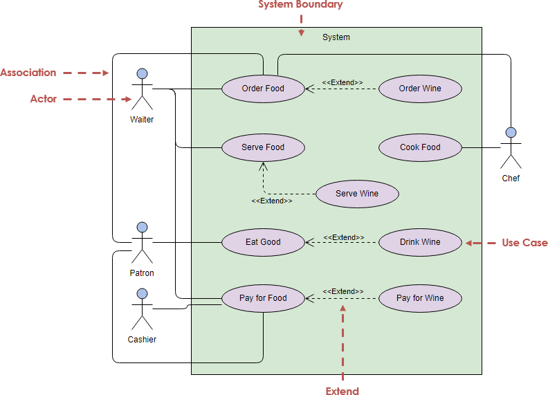
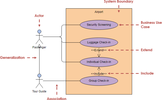
Example: This example depicts a model of several business use cases (goals) which represents the interactions between a restaurant (the business system) and its primary actors.
After the base use cases have been identified in the first cut, perhaps we could further structuring those use case with <> and <> use cases in the second round touch up as shown in the Figure below:
Business Use Case
A business use case is described in technology-free terminology which treats the business process as a black box and describes the business process that is used by its business actors, while an ordinary use case is normally described at the system functionality level and specifies the function or the service that the system provides for the user. In other words, business use case represents how the work to be done manually in the currently situation and it is not necessarily done by the system or intend to be automated in the scope of target system.
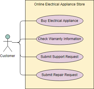
Use Case Diagram Examples
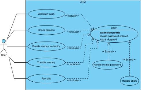
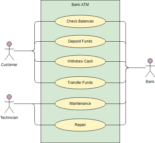
The figure below shows an ATM use case diagram example, which is quite a classic example to use in teaching use case diagram.
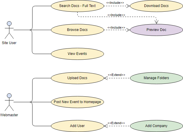
The Document Management System (DMS) use case diagram example below shows the actors and use cases of the system. In particular, there are include and extend relationships among use cases.
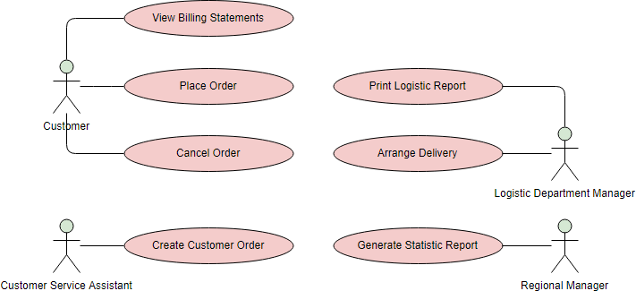
The Order System use case diagram example below shows the actors and use cases involved in the system:
🛠️ My Visual Paradigm Workflow: Tips That Actually Save Time
After years of modeling, here’s my streamlined approach in Visual Paradigm:
Quick Start
-
Start the Diagram: Go to
Diagram > Newand select Use Case Diagram. -
Add Elements: Use the left toolbar to drag an Actor or Use Case onto the canvas.
-
Fast Modeling: Hover over an actor and use the Resource Catalog (the small icon at the top-right of the shape) to drag out a new connection; this automatically creates and links a new Use Case.
-
AI Generation: You can use the AI tool to generate a starting diagram by providing a simple text description of your domain, like “ATM system”.
Advanced Features I Rely On
-
Flow of Events: Right-click a use case and select Use Case Details to write a step-by-step description of the user’s journey.
-
Wireframing: Link a Wireframe directly to a use case step to visualize the user interface for that specific action.
-
Requirement Links: Connect use cases to specific business requirements to ensure every technical feature has a clear purpose.
💡 Pro Tip: I always export diagrams as SVG for documentation and PNG for presentations. Visual Paradigm’s export options make this seamless.
🎯 New Conclusion: Why This Matters Beyond the Diagram
Use case diagrams aren’t just academic exercises—they’re communication tools that bridge gaps. In my experience:
✅ Stakeholders finally see what the system does without drowning in technical jargon.
✅ Developers get clear boundaries for implementation and testing.
✅ QA teams derive test scenarios directly from use case flows.
✅ Product owners prioritize features based on actor goals, not just technical complexity.
The real power isn’t in drawing perfect ovals and stick figures—it’s in the conversations the diagram sparks. When a business analyst, developer, and end-user can point to the same visual and say, “Yes, that’s what we’re building,” you’ve achieved alignment.
Visual Paradigm lowers the barrier to creating these diagrams without sacrificing UML rigor. Whether you’re documenting a legacy system migration or sketching a greenfield product, investing time in use case modeling pays dividends in reduced rework, clearer requirements, and happier teams.
Start simple. Iterate often. Let the diagram evolve with your understanding.
📚 Reference
- What is Use Case Diagram? – An introductory guide to Use Case Diagram: A foundational overview explaining the purpose, components, and benefits of use case diagrams in UML, ideal for beginners and practitioners alike.
- How to Identify Business Goals of an IT System: Practical guidance on aligning technical requirements with business objectives through use case modeling techniques.
- Beginner’s Guide to Use Case Diagrams with Visual Paradigm Online: Step-by-step tutorial for creating use case diagrams using Visual Paradigm’s cloud-based tool, with screenshots and workflow tips.
- Drawing a Use Case Diagram – User’s Guide: Official documentation detailing the mechanics of building use case diagrams in Visual Paradigm, including toolbar usage and element properties.
- UML Use Case Diagram Tutorial (Video): Visual walkthrough of use case diagram concepts and creation, suitable for visual learners and team training sessions.
- UML Use Case Diagram Tutorial – Lucidchart: Cross-tool reference explaining use case notation, relationships, and best practices with clear visual examples.
- Use Case Diagram Template and Examples – Study.com: Educational resource with templates, real-world examples, and explanations of use case diagram components for academic and professional use.
- Writing Effective Use Cases: Advanced guide on documenting use case scenarios, flow of events, and linking diagrams to detailed specifications.
- AI-Powered Diagram Generation in Visual Paradigm: Demonstration of using AI tools to accelerate use case diagram creation from natural language descriptions.
- Use Case Diagram Notations Guide – Visual Paradigm Circle: Comprehensive reference for all UML notations supported in use case diagrams, with OMG specification excerpts.
- Documenting Use Cases – User’s Guide: Instructions for enriching use cases with descriptions, pre/post-conditions, and alternative flows within Visual Paradigm.
- Visual Paradigm Use Case Tool Overview: Product page highlighting features of Visual Paradigm’s use case modeling capabilities, including collaboration and export options.
- Use Case Diagram Best Practices (Video): Expert tips on avoiding common pitfalls and maximizing the value of use case diagrams in agile and traditional projects.
- Use Case Diagrams for System Design (Video): Practical examples of applying use case diagrams to real-world system architecture and requirement gathering.