
Understanding the internal architecture of complex systems is a fundamental task in software and systems engineering. One of the most powerful tools for this purpose is the UML Composite Structure Diagram. While many practitioners are familiar with class diagrams or sequence diagrams, composite structure diagrams offer a unique perspective on how objects are constructed and how they interact internally. This guide addresses common inquiries regarding this diagram type, providing clear, technical explanations without unnecessary fluff.
What is a Composite Structure Diagram? 🤔
A Composite Structure Diagram is a structural diagram in the Unified Modeling Language (UML). It shows the internal structure of a classifier, such as a class or a component. Unlike a standard class diagram that focuses on attributes and operations, this diagram reveals the parts that make up the classifier, the connections between them, and the interfaces they expose.
Think of it as an X-ray of a system. It does not show the behavior (like a sequence diagram), but rather the anatomy of the static structure. It is particularly useful when dealing with complex objects that have significant internal organization.
- Focus: Internal composition and interaction.
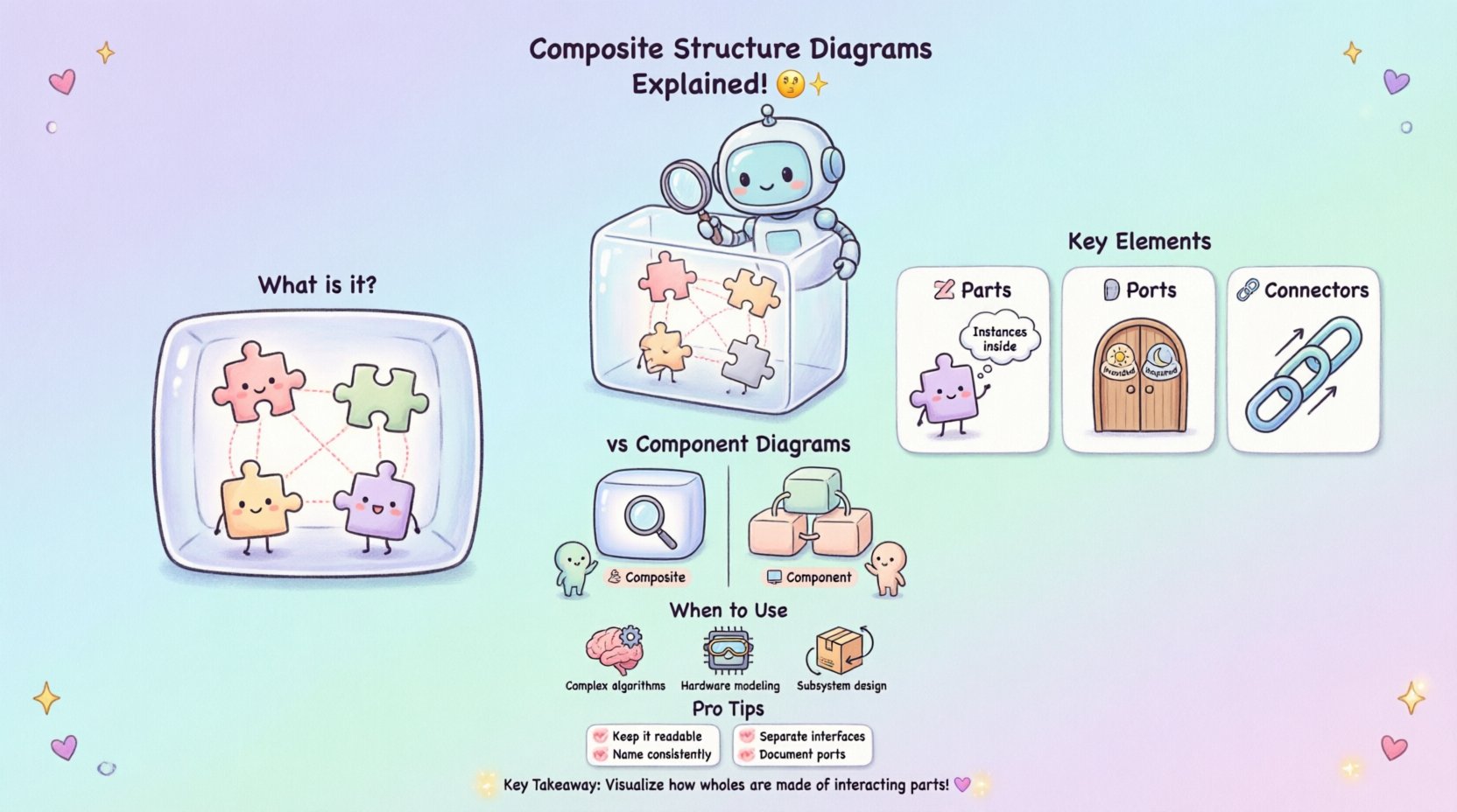
- Elements: Parts, ports, connectors, interfaces.
- Goal: Visualize how a whole is made of interacting parts.
Key Differences from Component Diagrams 🛠️
It is common to confuse Composite Structure Diagrams with Component Diagrams. While both deal with structure, their level of abstraction differs significantly.
| Feature | Composite Structure Diagram | Component Diagram |
|---|---|---|
| Scope | Internal structure of a single classifier | System-level architecture |
| Granularity | Parts and internal interactions | Software modules or executables |
| Usage | Designing complex objects | Deploying and linking modules |
| Detail | High detail on internal ports | High detail on dependencies |
Component diagrams operate at a higher level, often representing deployable units. Composite structure diagrams drill down into a specific class to show how it is built from other objects.
Core Notation and Elements 🔍
To read or create these diagrams effectively, one must understand the specific notation used. The visual language is precise.
1. Parts and Roles 🧩
Parts represent the instances of other classifiers contained within the composite. They are often shown as rectangles inside the main classifier box. A role name defines how the part is used within the composite structure.
- Part: The instance itself (e.g., engine).
- Role: The perspective the part plays (e.g., driveSystem).
2. Ports 🚪
Ports are interaction points on the boundary of a classifier. They define where communication happens. Without ports, parts would have to connect directly to the classifier boundary, which is often less flexible.
- Provided Port: Shows functionality offered to the outside world.
- Required Port: Shows functionality needed from the outside world.
3. Connectors 🔗
Connectors establish paths for communication. They link parts to ports or ports to other ports. They define the flow of data or control signals within the structure.
Frequently Asked Questions About Composite Structure Diagrams ❓
Below are detailed answers to the most common questions regarding the creation, interpretation, and utility of these diagrams.
1. When should I use a Composite Structure Diagram? 🕒
Use this diagram when the internal organization of a class or system is complex enough to warrant detailed visualization. Standard class diagrams often become cluttered when showing internal relationships. If you need to explain how a high-level object delegates work to sub-components, this diagram is the right choice.
- Complex Algorithms: When logic is distributed across multiple internal parts.
- Hardware Modeling: To show how software interacts with physical hardware parts.
- Subsystem Design: To define the boundary and internal wiring of a subsystem.
2. What is the difference between an Interface and a Port? 🎛️
This distinction is often a source of confusion.
- Interface: A contract that defines a set of operations. It specifies what can be done.
- Port: A physical or logical point of connection. It specifies where the interaction occurs.
Multiple interfaces can be realized by a single port. A port acts as a socket, while the interface is the plug shape that fits into it.
3. How do I represent internal communication? 📡
Internal communication is represented using connectors. These lines link parts to ports or parts to other parts. You can label these connectors to describe the type of data or signal being passed.
- Signal Flow: Use arrows to indicate direction.
- Data Flow: Label the connector with the variable or message type.
- Control Flow: Show how one part triggers another.
4. Can a composite structure diagram show multiple instances? 🔄
Yes, but it primarily shows the structure rather than the instance count. It defines the pattern. If you need to show specific runtime instances, you would typically supplement this with an object diagram. However, the composite structure diagram defines the blueprint for how those instances relate to each other.
5. How does this diagram help with refactoring? 🛠️
Refactoring involves changing the internal structure without changing the external behavior. This diagram is invaluable for this process.
- Identify Bottlenecks: See where internal connections are too dense.
- Decouple Parts: Use ports to separate interfaces from implementations.
- Verify Contracts: Ensure that all required interfaces are still satisfied after changes.
6. Is this diagram suitable for object-oriented design? 💻
Absolutely. In object-oriented design (OOD), objects are often composed of other objects. This diagram visualizes that composition relationship explicitly. It moves beyond simple aggregation and shows the wiring between them.
7. What tools are required to create these? 🖥️
Any modeling tool that supports UML 2.x standards can create these diagrams. There is no specific software requirement. The focus should remain on the modeling logic, not the tool used. Ensure the tool supports parts, ports, and connectors.
8. How do you handle lifecycle management in the diagram? ⏳
Composite structure diagrams are static. They do not show lifecycle states (like creation or destruction). For lifecycle concerns, combine this with a state machine diagram or a sequence diagram. The composite structure diagram shows the parts exist; the sequence diagram shows when they are created.
9. Can I nest composite structures? 🪆
Yes. A part within a composite structure can itself be a composite structure. This allows for hierarchical modeling. For example, a Car contains an Engine, and the Engine contains Pistons. You can represent this nesting to show deep structural relationships.
10. What happens if a part is optional? 🔌
Optional parts are represented by multiplicity indicators. You can specify a range like 0..1 on the part. This indicates that the part may or may not be present in a specific instance of the composite.
Best Practices for Clear Modeling 📝
To ensure these diagrams remain useful over time, follow these guidelines.
- Keep it Readable: Avoid creating diagrams that span multiple pages. If a structure is too complex, consider breaking it down into sub-diagrams.
- Consistent Naming: Ensure part names and role names follow the same naming convention throughout the project.
- Interface Separation: Keep interfaces distinct from implementation details to maintain flexibility.
- Use Stereotypes: If your tool supports them, use stereotypes to indicate specific types of parts (e.g., <<hardware>> or <<software>>).
- Document Ports: Clearly document what data flows through each port to avoid ambiguity.
Common Mistakes to Avoid 🚫
Even experienced modelers can make errors when working with composite structures.
1. Over-complicating the Internal View
Do not try to show every single attribute or method inside the composite box. Focus on the structure. If you need to show operations, use a standard class diagram.
2. Ignoring Port Directionality
Ensure you clearly mark provided versus required ports. Mixing these up can lead to design errors where a component expects a service it does not receive.
3. Confusing Aggregation with Composition
While composite structure diagrams imply composition, ensure you understand the difference between a part that is owned (composition) and a part that is merely referenced (aggregation). The diagram usually implies ownership, but the multiplicity clarifies the lifecycle.
4. Creating Circular Dependencies
Avoid connecting parts in a way that creates circular dependencies without a clear hierarchy. This can lead to infinite loops in logic or initialization failures.
Real-World Application Scenarios 🌍
Understanding the theory is one thing; applying it is another. Here is how these diagrams appear in different domains.
Embedded Systems
In embedded systems, a controller often has internal hardware modules. A composite structure diagram can show the microcontroller, the sensor interface, and the communication bus. This helps engineers understand signal flow before writing code.
Microservices Architecture
While often represented at a high level with component diagrams, microservices can be modeled internally. A single service might contain a database adapter, a caching layer, and an API gateway. A composite structure diagram clarifies how these internal pieces interact.
GUI Frameworks
User interface toolkits often use composite patterns. A window contains a panel, which contains buttons. A composite structure diagram helps visualize how events propagate from the button up to the window.
Integrating with Other Diagrams 🧩
Composite structure diagrams rarely stand alone. They work best as part of a larger modeling effort.
- Class Diagram: Use the class diagram for general attributes and methods. Use the composite diagram for the internal wiring of complex classes.
- Sequence Diagram: Use the sequence diagram to show the timing of interactions between the ports defined in the composite structure.
- Deployment Diagram: Once the internal structure is defined, map the deployable parts to the hardware in a deployment diagram.
Advanced Concepts: Behaviors and Protocols 📈
Some modeling standards allow for the inclusion of behavioral information within the composite structure. This is not standard in all UML tools but can be useful.
- Protocol State Machines: You can attach a state machine to a port to define how the port behaves when interacting.
- Interaction Constraints: You can add constraints to connectors to define rules about data flow (e.g., “must be encrypted”).
These advanced features add depth but should be used sparingly to prevent the diagram from becoming unreadable.
Summary of Key Takeaways 🏁
Composite structure diagrams provide a granular view of system anatomy. They bridge the gap between abstract class definitions and concrete implementation details. By focusing on parts, ports, and connectors, you can visualize complex interactions clearly.
Remember these core points:
- Use them for internal structure of complex classifiers.
- Distinguish clearly between interfaces and ports.
- Maintain simplicity to ensure the diagram remains a useful communication tool.
- Combine with other diagrams for a complete picture.
By adhering to these principles, you can leverage the full power of composite structure diagrams to design robust, maintainable, and well-organized systems.