
Creating a robust software system requires more than just writing code. It demands a clear understanding of how business goals translate into technical architecture. One of the most powerful tools for visualizing this translation is the Composite Structure Diagram. This specific type of UML diagram allows architects to see inside a class or component, revealing its internal parts, their relationships, and how they collaborate to fulfill external behaviors.
However, drawing a diagram is only half the battle. The real challenge lies in ensuring that every element within that diagram directly supports a stated business requirement. When these two domains—business needs and structural design—fall out of sync, the result is often technical debt, misaligned features, or systems that fail to deliver value.
This guide provides a deep dive into the methodology for aligning business requirements with a Composite Structure Diagram. We will explore the mechanics of internal structures, the role of ports and interfaces, and the practical steps to ensure your architecture reflects your organizational goals.
🔍 Understanding the Core Concepts
Before diving into the alignment process, it is essential to clarify what we are working with. Both business requirements and composite structures have specific definitions that guide the mapping process.
What is a Composite Structure Diagram?
A Composite Structure Diagram depicts the internal structure of a class or component. Unlike a standard Class Diagram that shows relationships between classes, this diagram focuses on the inside of a single unit. It breaks down complex systems into manageable pieces.
- Classifiers: The primary units being analyzed.
- Parts: The constituent elements within the classifier.
- Ports: Interaction points where the internal structure connects to the outside world.
- Connectors: Links between internal parts and ports.
- Interfaces: The defined contracts for communication.
What Defines Business Requirements?
Business requirements are high-level statements of the goals a system must achieve. They are not technical specifications; they are outcomes. Examples include “The system must process payments securely” or “Users must be able to retrieve reports in real-time.” These requirements drive the design decisions made within the Composite Structure Diagram.
🤝 Why Alignment Matters
When business requirements do not align with the composite structure, several issues arise. These issues are often costly to fix later in the development lifecycle.
1. Reduced Traceability
If a business requirement exists in the documentation but has no corresponding part or port in the diagram, there is no clear path to verify implementation. Alignment ensures that every requirement can be traced to a specific structural element.
2. Improved Maintainability
When the structure reflects the business logic, developers understand why a component exists. This makes future modifications safer. If a requirement changes, the architect can locate the specific part of the composite structure that needs adjustment.
3. Accurate Cost Estimation
Complex structures that do not serve a business requirement often lead to over-engineering. Aligning the diagram with requirements helps identify unnecessary complexity, allowing for more accurate resource planning.
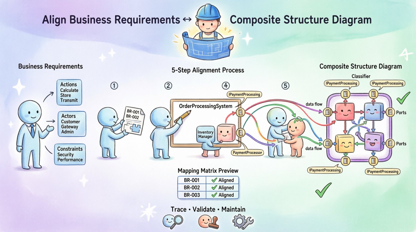
🚀 Step-by-Step Alignment Process
The following steps outline a systematic approach to mapping business requirements to the internal structure of a system component. This process moves from abstract needs to concrete structural definitions.
Step 1: Deconstruct the Business Requirements
Begin by reviewing the requirements list. Do not look at them as a whole; break them down into functional units. Look for keywords that imply data handling, user interaction, or external communication.
- Identify Actions: What does the system need to do? (e.g., Calculate, Store, Transmit)
- Identify Actors: Who or what interacts with the system? (e.g., Customer, Payment Gateway, Admin)
- Identify Constraints: Are there specific performance or security needs? (e.g., Low latency, Encrypted)
Write these down in a requirements traceability matrix. This document will serve as your checklist throughout the diagramming process.
Step 2: Define the Composite Context
Decide which class or component represents the scope of your Composite Structure Diagram. This is usually a central part of the system that manages complex internal logic. For example, an OrderProcessingSystem might be the composite, containing sub-parts like InventoryManager, PaymentProcessor, and NotificationService.
Ensure the scope is defined by the business requirements. If a requirement spans multiple systems, you may need multiple composite diagrams linked together.
Step 3: Identify Internal Parts
This is the core of the alignment. Map the functional units identified in Step 1 to Parts within your composite structure.
- Direct Mapping: If a requirement states “Manage Inventory,” create a part named
InventoryManager. - Abstraction: If a requirement is high-level, such as “Handle Security,” you might create a part named
SecurityHandlerthat encapsulates multiple lower-level checks. - Validation: Review every part. Does it serve a requirement? If a part exists without a requirement backing it, consider removing it to reduce complexity.
Step 4: Define Ports and Interfaces
Parts cannot interact with the outside world without Ports. Ports are the boundary between the internal structure and the external environment. Aligning ports with requirements is critical for defining the system’s API and integration points.
- Identify External Interactions: Based on the business requirements, list every external interaction. For example, “Receive credit card data” or “Send shipping confirmation.”
- Create Ports: Create a port for each interaction type. Name the port descriptively.
- Assign Interfaces: Define the interface that the port uses. This interface specifies the operations available on that port.
- Map Requirements: Link the requirement to the interface. For instance, Requirement BR-102 (Process Payment) maps to the
paymentPortinterfaceIPaymentProcessing.
Step 5: Connect Internal Parts
Once parts and ports are defined, you must determine how the parts work together to fulfill the requirement. Use Connectors to show data flow and control flow between parts.
- Collaboration: Show how the
InventoryManagercollaborates with theOrderManagerto fulfill a stock check requirement. - Delegation: If a port connects directly to an internal part, use a delegation connector. This indicates that the part fulfills the operation exposed by the port.
- Constraints: If a requirement specifies a constraint (e.g., “Must complete within 2 seconds”), document this as a constraint on the connector or the part.
📊 Mapping Matrix: Requirements to Structure
To ensure clarity, it is helpful to use a mapping matrix. This table helps visualize the relationship between the abstract requirement and the concrete diagram element.
| Requirement ID | Requirement Description | Target Composite Element | Element Type | Validation Status |
|---|---|---|---|---|
| BR-001 | System must authenticate users via OAuth | AuthHandler | Part | Aligned |
| BR-002 | System must expose user profile API | UserPort | Port (Interface: IUserAPI) | Aligned |
| BR-003 | Data must be cached for performance | CacheManager | Part | Aligned |
| BR-004 | System must log all security events | LoggerPort | Port (Interface: ILogging) | Aligned |
| BR-005 | System must support multi-language UI | LocalizationManager | Part | Aligned |
Using a table like this during the design phase ensures that no requirement is overlooked. If a requirement in the list has no corresponding row in the matrix, the alignment is incomplete.
⚙️ Deep Dive: Ports, Roles, and Interfaces
Understanding the nuances of Ports and Interfaces is crucial for accurate alignment. These are the specific mechanisms that bridge the gap between requirement and implementation.
Ports as Requirement Boundaries
A port is not just a connection; it is a boundary. It defines what the internal structure exposes to the outside. When a business requirement states “The system must accept data from a third-party vendor,” you must create a port for that vendor. If you fail to create a port, the internal structure is closed off, and the requirement cannot be met.
Roles and Multiplicity
Connectors between parts and ports have roles. A role defines the function of the part in that specific relationship. For example, a DatabasePart might have the role Reader when connected to a QueryPort and the role Writer when connected to a UpdatePort.
- Check Multiplicity: Ensure the number of required connections matches the requirement. If a requirement states “Support 5 concurrent users,” does your structure allow 5 simultaneous connections to the
SessionManagerpart? - Check Roles: Verify that the role names make sense in the context of the business domain. Avoid generic names like
Role1; useSupplierorConsumer.
Interfaces as Contracts
Interfaces define the operations available on a port. Aligning these with requirements means the interface operations should mirror the verbs in the business requirements.
- Requirement: “Send Email.”
- Interface Operation:
sendEmail(address, body)
If the requirement is “Send Email with Attachment,” the interface must include parameters for the attachment. This ensures the structure supports the full scope of the business need.
🛠️ Handling Internal Partitions
Composite Structure Diagrams often use Partitions to group internal parts. Partitions help organize the diagram logically, often mirroring the logical layers of the business application (e.g., Presentation Layer, Business Logic Layer, Data Layer).
Aligning Partitions with Business Domains
Do not create partitions arbitrarily. Align them with business domains or architectural layers.
- Domain-Driven Design: If your business uses Domain-Driven Design, create partitions based on Bounded Contexts.
- Layered Architecture: If the business requires strict separation of concerns, use partitions to separate Data Access from Business Logic.
When a requirement spans multiple layers, ensure the connectors cross the partition boundaries correctly. This visualizes the flow of data across the business domains.
🔎 Validation and Review
Once the diagram is drafted, you must validate it against the requirements. This is not a one-time check; it is an iterative process.
The Walkthrough Method
Conduct a walkthrough session with stakeholders. Use the diagram to explain how the system works. Ask the following questions:
- “Does this part handle the payment requirement?”
- “Is there a port for the external API mentioned in the spec?”
- “Can we trace this requirement to a specific element?”
If stakeholders cannot verify the requirement against the diagram, the alignment is weak. Revise the diagram until the traceability is clear.
Gap Analysis
Perform a gap analysis between the requirements document and the diagram elements.
- Take the list of requirements.
- Highlight every element in the diagram.
- Mark any requirement that lacks a corresponding element.
- Mark any element that lacks a corresponding requirement.
Resolve all gaps before finalizing the design. Unmarked requirements indicate missing functionality. Unmarked elements indicate waste.
🚧 Common Challenges and Solutions
Aligning business requirements with composite structures often presents specific hurdles. Below are common challenges and how to address them.
| Challenge | Impact | Solution |
|---|---|---|
| Abstract Requirements | Hard to map to specific parts | Create a dedicated part for the abstract logic (e.g., a Strategy Pattern part). |
| Complex Interfaces | Ports become cluttered | Use nested interfaces or delegate to sub-parts to simplify the main port. |
| Changing Requirements | Diagram becomes outdated | Version control the diagram and maintain a change log linked to requirements. |
| Over-Engineering | Too many parts for simple needs | Review the requirement necessity. Combine parts where business logic allows. |
🔄 Maintenance and Evolution
Business requirements evolve. A system is rarely static. The Composite Structure Diagram must evolve with it.
Versioning the Diagram
Treat the diagram as a living document. When a requirement changes:
- Update the Requirements Traceability Matrix.
- Identify the specific part or port that needs change.
- Modify the diagram.
- Notify the development team of the structural change.
Automated Tracing
If possible, use tools to automate the link between requirement IDs and diagram elements. This reduces manual errors and ensures that when a requirement is marked as “Completed,” the corresponding part is verified.
📝 Best Practices for Documentation
Clear documentation ensures that the alignment is understood by all team members, not just the architect.
- Use Consistent Naming: Ensure part names match the terminology used in the business requirements. If the business calls it a “Client,” do not name the part “UserEntity”.
- Annotate Connections: Add notes to connectors explaining the business logic flow. For example, “Validates credit limit before allowing transaction.”
- Include a Legend: Define what the different shapes and line styles mean in the context of your specific project.
- Link to Code: If the diagram is used during development, link diagram elements to the actual code repositories or modules.
🏁 Conclusion
Aligning business requirements with a Composite Structure Diagram is a discipline that requires precision, clarity, and continuous validation. It transforms abstract business goals into concrete architectural blueprints.
By following the steps outlined in this guide—deconstructing requirements, defining parts and ports, mapping interfaces, and validating against a matrix—you create a system architecture that is both robust and relevant. This alignment reduces risk, improves communication, and ensures that the final product delivers the value intended by the business stakeholders.
Remember, the diagram is not just a picture; it is a contract. It promises that the internal structure will fulfill the external needs. Treat it with the same rigor as the requirements themselves.