
System architecture requires precision. As technical leads, you often face the challenge of communicating how complex internal structures function within a larger ecosystem. While Class diagrams show relationships and Component diagrams show high-level blocks, there is a specific need for visibility into the internal collaboration of a classifier. This is where the Composite Structure Diagram becomes essential. This guide explores the specific scenarios, structural requirements, and decision criteria that dictate when this UML artifact is necessary versus when it introduces unnecessary complexity.
Understanding internal structure allows teams to validate interface contracts, verify port configurations, and ensure that delegation connectors align with the intended data flow. However, these diagrams are not a universal solution. They serve a specific purpose: revealing the anatomy of a complex class or component. This document provides the technical depth required to make informed decisions about their application.

🧩 Understanding the Anatomy of a Composite Structure Diagram
A Composite Structure Diagram visualizes the internal structure of a classifier. It breaks down a class or component into its constituent parts. These parts interact through interfaces, defined as ports. The diagram focuses on the internal wiring rather than external behavior.
🔹 Key Structural Elements
- Composite Classifiers: These are the containers. They represent the class or component being dissected. They hold the internal structure.
- Parts: These are the internal instances. A part is a specific role played by a classifier within the composite. It has a defined type.
- Ports: These are interaction points. Ports define where a part connects to the outside world or to other internal parts. They enforce interface contracts.
- Connectors: These link parts to ports. They represent the flow of data or control between internal elements.
- Internal Allocations: These show how resources or control are distributed across the structure.
- Delegation Connectors: These link an external port to an internal port. They allow the composite to expose the functionality of an internal part without revealing the internal complexity.
Visualizing these elements helps in identifying potential bottlenecks. For instance, if a single part is required to handle all external requests via a delegation connector, that part becomes a critical point of failure. The diagram makes this dependency explicit.
🧭 The Decision Framework for Technical Leads
Adopting this diagram type is a strategic choice. It consumes documentation time and cognitive load. You must weigh the benefits of internal visibility against the cost of maintenance. The following criteria help determine necessity.
📌 Criteria for Adoption
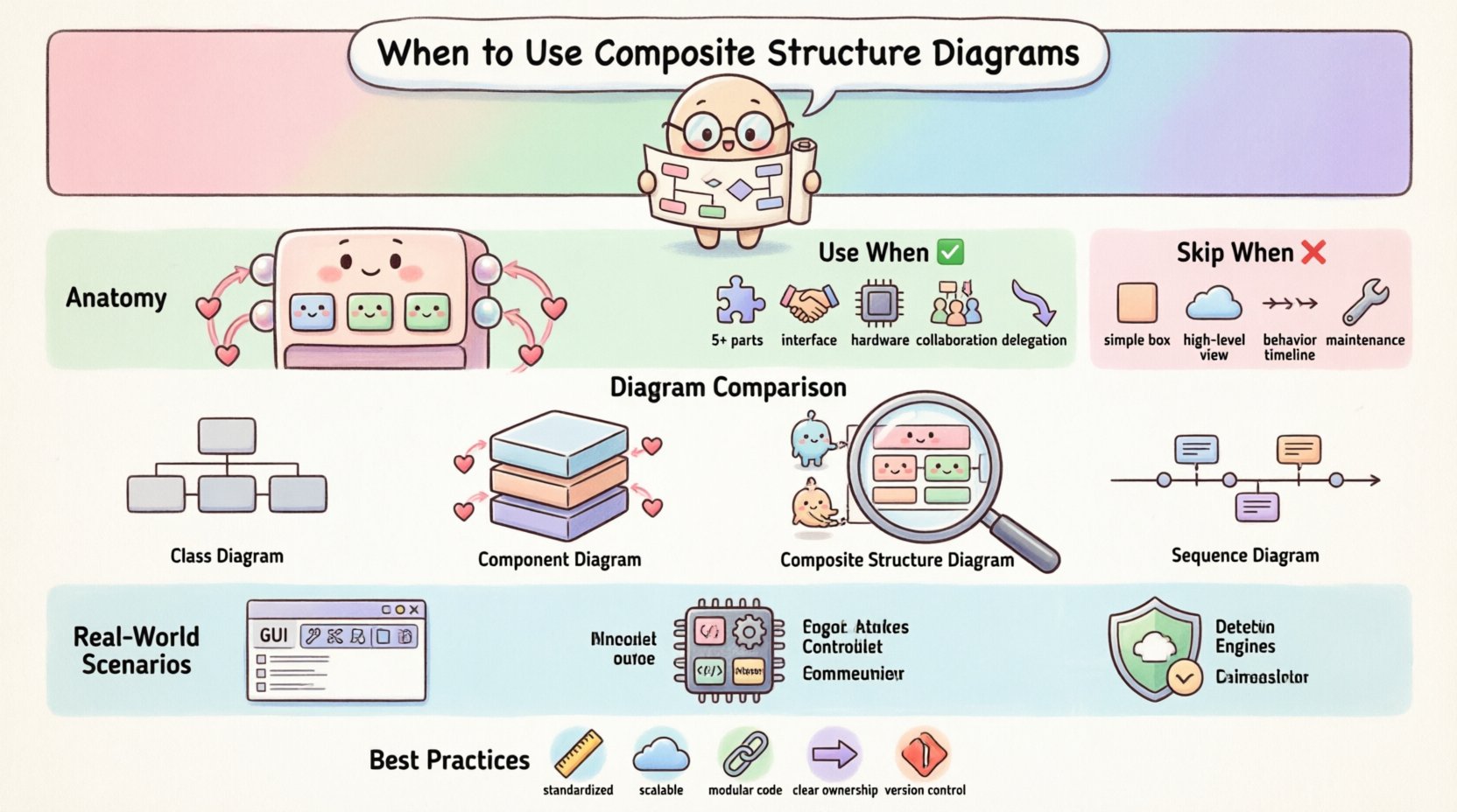
- Complexity Threshold: If a class contains more than five internal parts or complex interaction logic, a standard class diagram may fail to convey the structure adequately.
- Interface Sensitivity: If the system relies heavily on strict interface contracts where a change in one part affects the whole, internal wiring must be documented.
- Hardware Constraints: In embedded systems or resource-constrained environments, showing how parts map to physical or logical resources is often critical.
- Collaboration Patterns: If the design relies on specific patterns like Mediator or Facade where internal parts collaborate significantly, the structure must be clear.
- Delegation Requirements: If the system uses delegation to hide implementation details from external clients, this diagram validates the delegation paths.
📌 Criteria for Avoidance
- Simple Aggregation: If a class simply holds a reference to another object without complex internal interaction, a standard association is sufficient.
- High-Level Architecture: For system-level views, Component or Deployment diagrams provide better abstraction than internal class structures.
- Dynamic Behavior Focus: If the focus is on state changes or message sequencing, Sequence or State diagrams are more appropriate.
- Low Maintenance Budget: These diagrams are prone to becoming outdated quickly if the internal structure changes frequently. If refactoring is constant, maintainability may suffer.
📊 Comparison Matrix: Diagram Types
Selecting the right tool requires understanding the scope of each artifact. The table below contrasts the Composite Structure Diagram with other common UML diagrams.
| Diagram Type | Primary Focus | Best Used For | Complexity Level |
|---|---|---|---|
| Class Diagram | Static structure, attributes, methods | General object relationships | Low to Medium |
| Component Diagram | High-level modules, dependencies | System decomposition | Medium |
| Composite Structure Diagram | Internal parts, ports, connectors | Internal collaboration, interface contracts | High |
| Sequence Diagram | Time-ordered interactions | Behavioral flow, message passing | Medium to High |
Notice that the Composite Structure Diagram sits at a higher complexity level. It is not a replacement for the Class Diagram but a supplement. It answers questions the Class Diagram cannot: How do the internal parts talk to each other?
🚀 Scenario Analysis: Real-World Applications
Technical decisions are best made through concrete examples. Consider the following scenarios where this diagram adds value.
🖥️ Scenario 1: Complex User Interface Composition
In a GUI framework, a Window component might contain a Toolbar, a MenuBar, and a ContentPane. Each of these is a part. The Window class must define ports for user input. A delegation connector might route a mouse click from the Window port to the ContentPane part. Without a Composite Structure Diagram, this routing logic remains implicit in the code. The diagram makes it explicit, helping developers understand where to inject custom event handlers.
⚙️ Scenario 2: Embedded Control Systems
An embedded controller for a motor drive system might have a PowerManager part, a SensorReader part, and a CommunicationInterface part. The CommunicationInterface port must handle external commands. If the PowerManager part fails, the CommunicationInterface must report the status. The diagram clarifies the dependency between the SensorReader and the PowerManager. It ensures that the internal allocation of resources respects the timing constraints of the motor.
🔒 Scenario 3: Security Boundary Enforcement
In a security module, a Firewall component might contain an InspectionEngine and a LoggingService. External requests enter through a specific port. The InspectionEngine processes the request. If it passes, it is delegated to the LoggingService. The diagram visualizes the trust boundaries. It shows which parts are exposed to the network and which are internal only. This is crucial for security audits.
⚠️ Common Pitfalls and Anti-Patterns
Even with good intentions, documentation can become a burden. Technical leads must avoid these common errors.
- Over-Diagramming: Do not diagram every class. If a class has no internal structure, a Composite Structure Diagram is redundant. Stick to classes that exhibit complex internal collaboration.
- Naming Confusion: Ensure clear distinction between Ports and Interfaces. A Port is a point of interaction; an Interface is a contract. Confusing them leads to implementation errors.
- Ignoring Multiplicity: Parts can have multiplicities. A single Window can have zero or more Toolbar parts. Failing to document this leads to runtime errors regarding object instantiation.
- Static Assumptions: Assuming parts are static. In dynamic systems, parts might be created at runtime. The diagram should note if parts are dynamic or static.
- Loss of Context: A diagram showing internal parts without showing how it connects to the external system is useless. Always include the external ports that interact with the environment.
🛡️ Best Practices for Implementation
To maximize the value of these diagrams, follow these operational guidelines.
- Standardize Notation: Ensure the team agrees on how to represent ports and connectors. Consistency reduces cognitive load.
- Keep It Abstract: Do not include every attribute. Focus on the structural relationships. If a part has 50 attributes, just list the part name and type.
- Link to Code: Ensure the diagram maps directly to the source code structure. If the code refactors the internal parts, the diagram must update immediately.
- Use Delegation Wisely: Only use delegation connectors when you need to expose an internal part’s interface externally. Do not use them for internal-only communication.
- Version Control: Store these diagrams in version control alongside the code. Treat them as living artifacts, not one-off documents.
🔗 Integrating with Other UML Artifacts
A Composite Structure Diagram does not exist in isolation. It interacts with other modeling artifacts to form a complete picture.
- Class Diagrams: The composite classifier itself is defined in a Class Diagram. The Composite Structure Diagram expands on this definition.
- Sequence Diagrams: Use Sequence Diagrams to describe the flow of messages that enter the ports defined in the Composite Structure Diagram.
- Deployment Diagrams: Map the physical deployment of the composite classifier to the logical structure shown in the diagram.
- State Machine Diagrams: If a part changes state based on internal interactions, link the State Machine to the specific part within the composite.
📝 Final Thoughts on Structural Clarity
The decision to use a Composite Structure Diagram comes down to the necessity of visibility. When internal collaboration is complex enough to obscure the system’s behavior, this diagram provides the necessary lens. It transforms implicit code logic into explicit architectural contracts.
Technical leads must balance the need for detail with the risk of documentation decay. If the internal structure is stable and critical to the system’s integrity, the investment is justified. If the structure is fluid and the focus is on external behavior, other artifacts may serve better.
Ultimately, the goal is clarity. Whether you choose this diagram or another, the objective remains the same: ensuring that every team member understands how the system is built and how it functions internally. By adhering to the criteria outlined in this guide, you can determine when this specific tool enhances the architectural narrative and when it detracts from it.