
Composite Structure Diagrams (CSD) are a critical tool within the Unified Modeling Language (UML) suite. They allow architects to visualize the internal structure of a classifier and the interactions between its constituent parts. Understanding component relationships is fundamental to building robust, scalable, and maintainable software systems. This guide explores the mechanics of these relationships, ensuring clarity in system design without the need for specific tooling.
Understanding the Core Purpose of Composite Structure Diagrams 🏗️
A Composite Structure Diagram focuses on the internal composition of a class or component. Unlike a standard Class Diagram, which shows attributes and methods, a CSD reveals how parts fit together to form a whole. It answers the question: “What makes up this system, and how do they talk to each other?”.
The primary value lies in defining the contract between the internal parts and the external environment. By modeling these relationships explicitly, teams can prevent coupling issues and ensure that interfaces are correctly implemented. The diagram provides a blueprint for code generation and integration testing.
Key Benefits of Modeling Internal Structure
- Clarity: Visualizes complex internal logic that standard class diagrams obscure.
- Contract Definition: Clearly defines provided and required interfaces.
- Decoupling: Helps identify tight dependencies early in the design phase.
- Reusability: Allows parts to be reused across different composite structures.
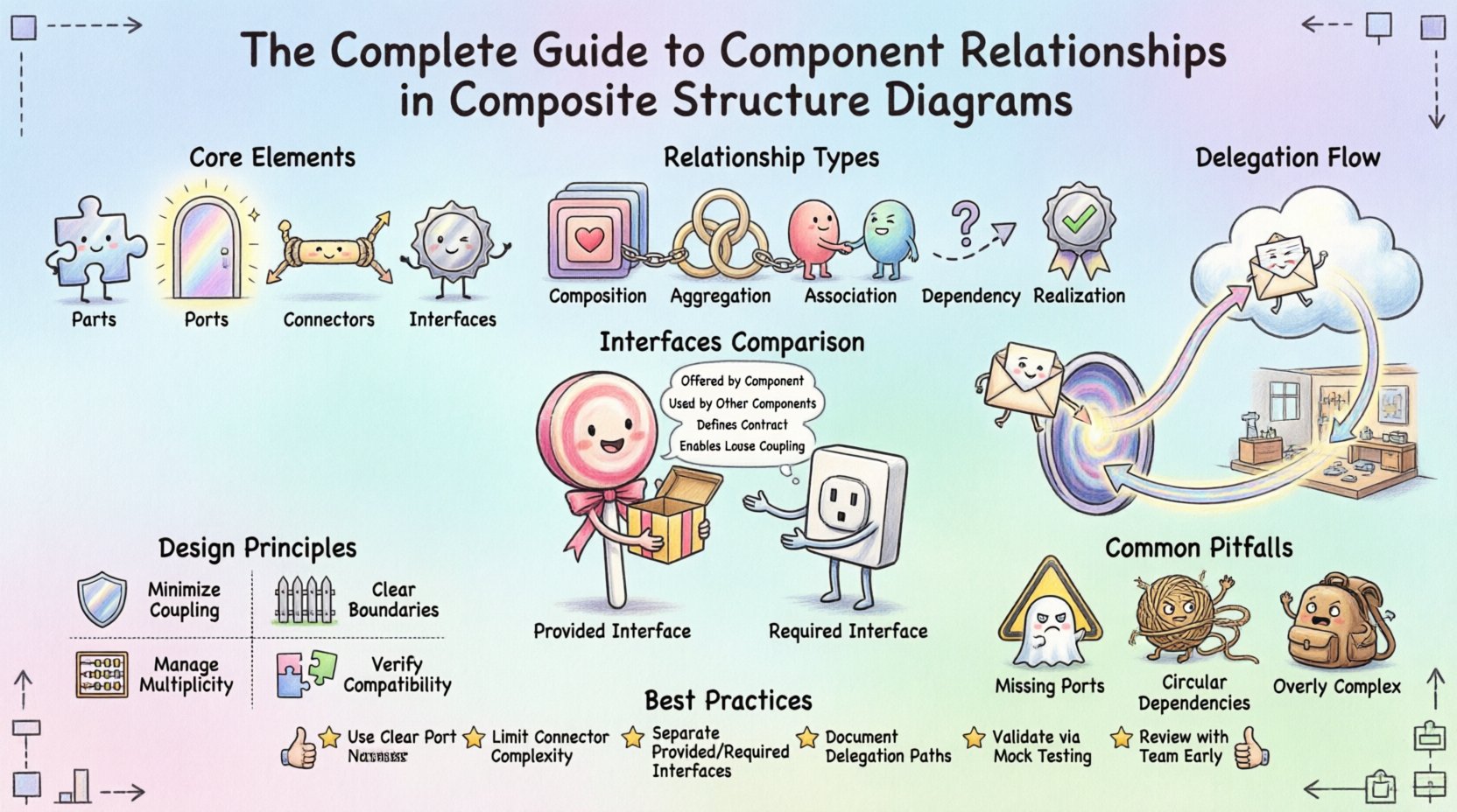
Core Elements of a Composite Structure Diagram 🧩
Before diving into relationships, one must understand the building blocks. A CSD consists of specific elements that interact to define the system’s behavior.
1. Parts and Roles
A Part represents an instance of a classifier that is contained within a composite structure. It is a specific component of the whole. A Role is the interface that a part plays within the context of the composite structure. This distinction allows the same class to play different roles in different contexts.
2. Ports
Ports are interaction points on a part or the composite structure itself. They serve as the entry and exit points for interactions. A port defines the interaction point where a part connects to the outside world or to other parts.
3. Connectors
Connectors bind parts together. They define the path through which messages flow. Connectors link ports on one part to ports on another, or to the ports of the composite structure itself.
4. Interfaces
Interfaces define a set of operations that a part can provide or require. In a CSD, interfaces are often attached to ports to specify the exact contract of communication.
Types of Relationships and Connections 🔗
The heart of a Composite Structure Diagram lies in the relationships between its elements. These relationships dictate how data flows and how control is managed within the system.
1. Containment Relationships (Composition and Aggregation)
These relationships define the structural hierarchy. They specify which parts belong to which composite.
- Composition: A strong form of aggregation where the part cannot exist independently of the whole. If the composite structure is destroyed, the parts are destroyed.
- Aggregation: A weaker relationship where parts can exist independently. The composite structure manages the lifecycle but does not own the parts exclusively.
2. Association Relationships
Associations link parts together to indicate a structural relationship. In the context of CSDs, these are often realized through connectors. They define the multiplicity of the relationship, such as one-to-many or many-to-many.
3. Dependency Relationships
Dependencies indicate that a change in one element may affect another. In CSDs, this is often seen when a part requires an interface provided by another part but does not necessarily own it.
4. Realization Relationships
This relationship shows that a part or port implements a specific interface. It is a contract fulfillment. If a port is marked as realizing an interface, it must provide all operations defined in that interface.
Interfaces: Provided vs. Required 🎯
Understanding the flow of requirements is essential for correct relationship mapping. Interfaces are categorized based on whether they are offered or needed.
Provided Interfaces
A provided interface is one that a part offers to the outside world. It is a capability. When modeling a component, you must define what services it exposes. This allows other parts to utilize its functionality without needing to know its internal implementation details.
Required Interfaces
A required interface is one that a part needs to function correctly. It represents a dependency on external functionality. If a part requires a specific interface, it cannot operate unless that interface is available within the composite structure.
Comparison of Interface Types
| Feature | Provided Interface | Required Interface |
|---|---|---|
| Direction | Outbound from the part | Inbound to the part |
| Ownership | Owned by the part | Needed by the part |
| Dependency | Independent of consumer | Dependent on provider |
| Symbol | Full circle (Lollipop) | Open circle (Socket) |
Connectors and Delegation 🔄
Connectors are the physical representation of relationships in a diagram. They bridge the gap between abstract interfaces and concrete parts.
Direct Connectors
Direct connectors link a required interface on one part directly to a provided interface on another part. This is the simplest form of interaction. It implies that the two parts are tightly coupled in terms of communication.
Delegation Connectors
Delegation is a specific type of connector used to pass messages from an internal part to the external environment, or vice versa. This is crucial for maintaining the encapsulation of the composite structure.
- External to Internal: A message enters the composite structure via a port and is delegated to an internal part that handles the logic.
- Internal to External: An internal part performs a task and delegates the result back to the external port to be sent to the caller.
Delegation connectors allow the internal parts to remain hidden. The external world interacts with the composite structure’s port, not the individual parts directly. This supports the principle of information hiding.
Designing Robust Component Interactions 🛡️
When modeling relationships, adherence to certain design principles ensures the longevity of the system. Poorly defined relationships lead to spaghetti code and fragile architectures.
1. Minimize Coupling
Every connection represents a point of failure or change. Aim to reduce the number of connectors between parts. Use interfaces to abstract dependencies. If Part A needs to talk to Part B, define an interface for the interaction rather than calling methods directly.
2. Define Clear Boundaries
Ensure that each part has a single responsibility. A part that does too many things will require too many interfaces and connectors. Keep the scope of a part narrow and focused.
3. Manage Multiplicity
Specify the number of instances involved in a relationship. A one-to-one relationship is different from a one-to-many relationship. Incorrect multiplicity can lead to runtime errors or resource exhaustion.
4. Verify Interface Compatibility
Ensure that the operations in a required interface match the operations in the provided interface. If Part A requires a method calculate(), Part B must provide a method with the same signature.
Common Pitfalls in CSD Modeling ⚠️
Even experienced architects can make mistakes when defining relationships. Being aware of common errors helps in avoiding architectural debt.
- Missing Ports: Connecting parts directly to other parts without using ports. This bypasses the interface contract and creates tight coupling.
- Incorrect Delegation: Failing to delegate messages from internal parts to external ports. This makes the internal parts visible to the outside world, violating encapsulation.
- Circular Dependencies: Creating loops where Part A requires Part B, and Part B requires Part A. This can lead to initialization errors and infinite loops.
- Overly Complex Structures: Creating a composite structure that is too large. If a diagram becomes unreadable, consider breaking it down into sub-structures.
- Ignoring Lifecycle: Not defining whether parts are owned (Composition) or shared (Aggregation). This affects memory management and resource cleanup.
Best Practices for Relationship Management 📝
To maintain a clean and effective model, follow these guidelines when defining relationships.
Use Stereotypes for Clarity
Extend the diagram with stereotypes to denote specific types of relationships. This helps in communicating intent to other team members. For example, use a stereotype to indicate a factory pattern or a singleton part.
Document Interface Contracts
Do not rely solely on the diagram. Document the behavior expected by the interfaces. A diagram shows structure; documentation shows behavior. Together, they form a complete specification.
Validate with Stakeholders
Review the relationships with the development team. Ensure that the modeled connections match the actual implementation plans. Discrepancies between design and code lead to refactoring later.
Iterate on the Design
Composite Structure Diagrams are not static. As requirements change, the internal structure may need to evolve. Update the relationships to reflect the new reality. Do not let the diagram become outdated documentation.
Advanced Scenarios and Use Cases 🚀
Understanding basic relationships is one thing; applying them to complex scenarios is another. Here are a few scenarios where precise relationship modeling is critical.
Scenario 1: Plugin Architecture
In a plugin system, the core application provides a set of required interfaces. Plugins provide implementations for these interfaces. The CSD must show the core application delegating calls to the plugin ports. This ensures that plugins can be added or removed without breaking the core.
Scenario 2: Microservices Communication
When modeling microservices, each service is a composite structure. The relationships between services are defined via connectors that represent network calls. Internal components within a service use ports to communicate with the service boundary. This separation ensures that internal changes do not impact external consumers.
Scenario 3: Hardware-Software Integration
In embedded systems, parts often represent physical hardware components. Relationships must reflect physical constraints. A power supply part might be composed of multiple battery cells. The CSD helps visualize how the software interacts with the hardware ports to control power states.
Summary and Next Steps 📈
Mastering the relationships within a Composite Structure Diagram requires a deep understanding of parts, ports, and interfaces. By carefully defining how these elements interact, architects can create systems that are modular, maintainable, and scalable.
Focus on the following key takeaways:
- Structure Matters: The internal composition defines the external behavior.
- Interfaces are Contracts: Clearly define provided and required interfaces to manage dependencies.
- Delegation Protects Encapsulation: Use delegation connectors to hide internal details.
- Validate Relationships: Ensure that multiplicity and lifecycle rules are correctly applied.
As you proceed with your design projects, apply these principles to your Composite Structure Diagrams. Review your models for unnecessary complexity and ensure that every connector serves a clear purpose. This disciplined approach leads to software architectures that stand the test of time.