
Software architecture relies heavily on clear communication between stakeholders. While class diagrams describe static structures and sequence diagrams describe dynamic behavior, the Composite Structure Diagram (CSD) offers a unique view. It reveals the internal organization of a classifier. This includes parts, ports, roles, and connectors. Understanding how to create these diagrams effectively is crucial for maintaining complex systems.
Designing a composite structure diagram requires precision. It is not merely about drawing boxes. It is about defining the contract between the container and its constituents. This guide outlines ten best practices. Each practice addresses a specific aspect of modeling internal structure. By following these guidelines, you ensure clarity and reduce ambiguity in your technical documentation.
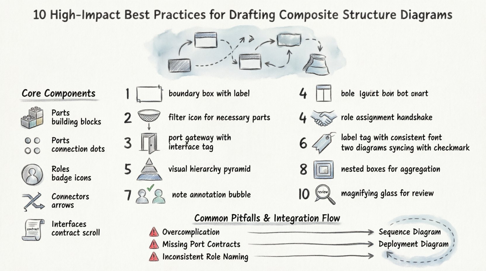
Understanding the Core Components 🧩
Before applying best practices, one must understand the building blocks. A composite structure diagram focuses on the internal parts of a classifier. The following elements are fundamental:
- Parts: Instances of classifiers that make up the composite structure.
- Ports: Interaction points where the composite structure interacts with its environment or other parts.
- Roles: Represent the responsibilities a part plays within the composite structure.
- Connectors: Links that define the communication paths between parts and ports.
- Interfaces: Define the contract for interaction at a port.
Using these components correctly establishes the foundation for a robust model. When these elements are misaligned, the diagram fails to communicate the intended design.
10 Best Practices for Drafting Composite Structure Diagrams 📋
The following practices provide a structured approach to creating effective diagrams. These steps prioritize readability, maintainability, and accuracy.
1. Define Clear Boundaries for the Classifier 📐
Every composite structure diagram represents a specific classifier. This classifier acts as the container. The boundary of this container must be clearly defined. A rectangular box represents the classifier. Inside this box, the internal structure resides.
- Ensure the outer boundary is distinct from the surrounding context.
- Label the classifier name prominently at the top.
- Avoid overlapping boundaries with other diagrams in the same document.
Clear boundaries prevent confusion about what is internal versus what is external. This distinction is vital when analyzing system dependencies.
2. Identify Necessary Parts Only 🧱
Overloading a diagram with too many parts obscures the main logic. Select only the parts that are essential to the function of the composite structure.
- List the parts based on their functional necessity.
- Exclude parts that are implementation details not relevant to the architecture level.
- Group related parts logically to reduce visual clutter.
Focusing on necessity keeps the diagram high-level. This allows stakeholders to grasp the composition without getting lost in minor details.
3. Specify Interaction Points (Ports) Accurately ⚡
Ports are the gateways for data and control flow. They define how the composite structure communicates. Inaccurate port specifications lead to integration errors later in the development lifecycle.
- Label each port with a clear name.
- Specify the interface type required or provided by the port.
- Ensure the port type matches the expected data flow.
Accurate port definitions act as a contract. They tell other developers exactly how to interact with this component.
4. Map Roles Correctly to Parts 🤝
A part might play multiple roles within a structure. A role defines the specific responsibility of that part. Mapping roles correctly clarifies the behavior of each constituent.
- Assign a role name that describes the function (e.g., Writer, Reader).
- Connect the role to the specific port or part it represents.
- Ensure the role aligns with the interface it implements.
Correct role mapping prevents ambiguity. It ensures that every part knows its place and responsibility within the system.
5. Maintain Visual Hierarchy 🏛️
Visual hierarchy guides the eye through the diagram. Important elements should be prominent. Less critical details should be secondary.
- Use consistent sizing for parts of the same type.
- Place the primary parts in the center of the structure.
- Use lines and spacing to group related components.
A well-organized visual hierarchy reduces cognitive load. Readers can scan the diagram and understand the structure quickly.
6. Standardize Labeling Conventions 🏷️
Consistency in naming is key for maintainability. If labels vary randomly, the diagram becomes difficult to read.
- Use a consistent naming convention for all parts and ports.
- Keep labels concise but descriptive.
- Ensure labels match the terminology used in the codebase.
Standardized labeling aids in cross-referencing. When a developer reads the code, they should recognize the names in the diagram immediately.
7. Ensure Consistency with Class Diagrams 📊
The composite structure diagram should not contradict the class diagram. The class diagram defines the types. The composite structure diagram defines the instances and their relationships.
- Verify that part types match the classes defined elsewhere.
- Ensure attributes and methods align between diagrams.
- Update both diagrams simultaneously if changes occur.
Consistency across diagrams builds trust. It ensures that the architectural view is accurate and up-to-date.
8. Manage Complexity with Aggregation 🧩
Complex systems often require nested structures. Aggregation allows you to define a composite structure within another composite structure.
- Use nested diagrams for sub-systems that are too complex for one view.
- Limit the depth of nesting to avoid confusion.
- Provide a summary view for the top-level structure.
Managing complexity prevents the diagram from becoming an unreadable web. Aggregation keeps the high-level view clean while allowing deep dives when needed.
9. Document Internal Logic Explicitly 📝
Some internal logic cannot be shown through structure alone. Annotations or notes help clarify specific behaviors.
- Use notes to explain complex connectors.
- Add comments regarding state changes if relevant.
- Link to external documentation for detailed algorithmic logic.
Explicit documentation bridges the gap between structure and behavior. It ensures that the design intent is preserved.
10. Review for Redundancy Regularly 🔍
As systems evolve, diagrams can become cluttered. Regular reviews help identify redundant elements.
- Check for duplicate parts that serve the same purpose.
- Remove unused ports or roles.
- Consolidate similar connectors where possible.
Regular reviews keep the diagram lean. A lean diagram is easier to maintain and understand over time.
Common Pitfalls and Solutions ⚠️
Avoiding mistakes is just as important as following best practices. The table below outlines common issues and how to resolve them.
| Pitfall | Impact | Solution |
|---|---|---|
| Unclear Port Interfaces | Integration failures between components. | Explicitly define interface types on all ports. |
| Too Many Parts | Diagram becomes unreadable and cluttered. | Use aggregation to group parts into sub-structures. |
| Inconsistent Naming | Confusion between diagram and code. | Adopt a strict naming convention policy. |
| Missing Connectors | Data flow paths are undefined. | Trace all data flows and add corresponding connectors. |
| Contradicting Class Diagrams | Architectural inconsistency. | Synchronize updates across all diagram types. |
Integrating CSD into the Workflow 🔄
Composite Structure Diagrams are not created in isolation. They fit into a larger modeling workflow. To be effective, they must be integrated with other UML diagrams.
With Class Diagrams
Class diagrams define the blueprint. Composite structure diagrams define the instance composition. Use the class diagram to verify types. Use the composite structure diagram to verify relationships.
With Sequence Diagrams
Sequence diagrams show the flow of messages. Composite structure diagrams show where those messages go. Ensure that the ports in the CSD match the participants in the sequence diagram.
With Deployment Diagrams
Deployment diagrams show physical nodes. Composite structure diagrams show logical nodes. Ensure that the logical parts map to the correct physical artifacts.
Refining the Diagram for Maintenance 🛠️
Once the diagram is drafted, it requires maintenance. Software evolves, and the diagram must evolve with it.
- Version Control: Treat the diagram file like code. Use version control to track changes.
- Change Logs: Document significant changes to the structure.
- Review Cycles: Schedule regular reviews during sprint planning or design meetings.
Maintenance ensures the diagram remains a valid source of truth. An outdated diagram can lead to more errors than no diagram at all.
Looking Ahead: Future Considerations 🔮
As software architectures grow more distributed, the need for clear internal structure models increases. Microservices, cloud-native architectures, and event-driven systems all benefit from precise structural definitions.
- Consider how parts map to services in a microservice architecture.
- Define ports to represent API endpoints clearly.
- Ensure roles align with service responsibilities.
The principles of the composite structure diagram remain relevant. They provide a way to decompose complexity. By adhering to these best practices, you create models that stand the test of time.
Summary of Key Takeaways ✅
To summarize, creating an effective composite structure diagram involves:
- Defining clear boundaries and necessary parts.
- Specifying accurate ports and roles.
- Maintaining visual hierarchy and labeling standards.
- Ensuring consistency with other diagrams.
- Managing complexity through aggregation.
- Documenting logic and reviewing for redundancy.
These steps form a comprehensive approach. They help you communicate complex internal structures clearly. The goal is clarity, not complexity. By focusing on the essential elements, you create diagrams that aid understanding rather than hindering it.
Apply these practices to your next modeling task. Start with a clear boundary and build inward. Ensure every part has a purpose. Verify every connection. This disciplined approach leads to better software architecture.
Remember, the diagram is a tool for communication. It serves the team and the project. Keep it clean, keep it accurate, and keep it updated. These habits will pay dividends throughout the development lifecycle.