
Designing a robust composite structure is critical for the longevity and performance of any complex system. Whether you are mapping out software architecture or engineering physical components, identifying weak links early prevents catastrophic failures later. This guide provides a comprehensive approach to analyzing, diagnosing, and resolving structural vulnerabilities within your composite diagrams. We will explore common failure points, practical troubleshooting steps, and strategies to reinforce your design integrity without relying on specific proprietary tools.
🧩 Understanding the Composite Structure Diagram
A composite structure diagram serves as a blueprint for the internal organization of a classifier or system component. Unlike simpler class diagrams, this visualization delves deeper into how parts interact within a defined boundary. It reveals the arrangement of internal components, their roles, and the interfaces through which they communicate. When a design lacks cohesion or contains poorly defined connections, weak links emerge.
These weak links often manifest as bottlenecks, high coupling, or ambiguous data flow. Recognizing the anatomy of a composite structure is the first step toward troubleshooting. Key elements include:
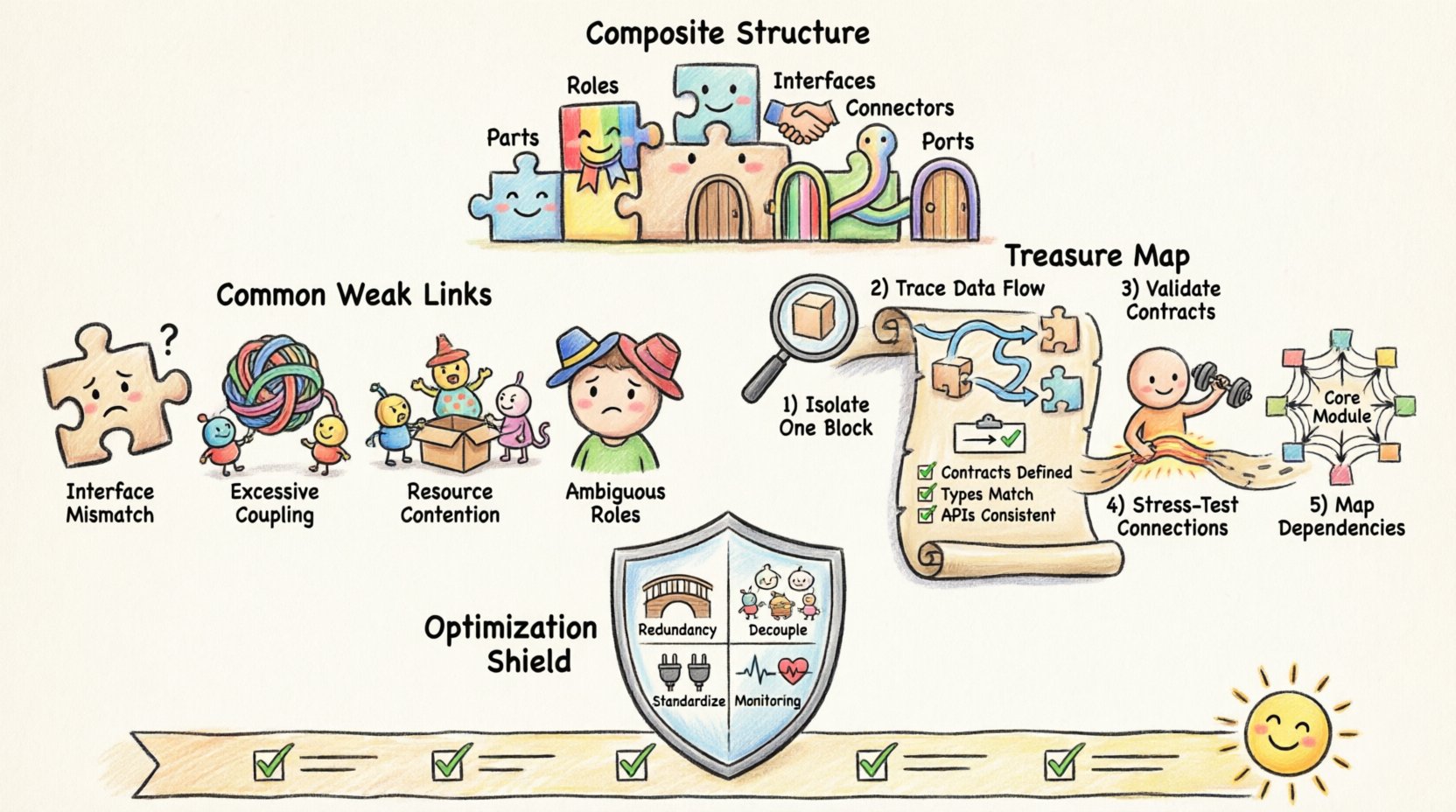
- Parts: The individual components that make up the whole.
- Roles: The specific functions a part performs within the structure.
- Interfaces: The contracts defining how parts interact.
- Connectors: The physical or logical paths linking parts and interfaces.
- Ports: The points of interaction where connections are established.
When any of these elements are misconfigured, the entire system’s stability is compromised. A weak link in the connector layer can render a perfectly functional component useless if it cannot transmit data effectively.
⚠️ Identifying Common Weak Links
Weak links do not always appear obvious. They often hide in plain sight within complex diagrams. Below is a breakdown of frequent issues that compromise structural integrity.
1. Interface Mismatches
One of the most prevalent issues occurs when an interface requires a service that a connected component does not provide. This creates a logical gap where data or commands are expected but never received. Over time, this leads to system hangs or silent failures.
2. Excessive Coupling
When components are tightly coupled, changing one part requires significant rework across multiple other parts. This rigidity makes the structure fragile. If a weak link in a coupled component fails, the impact ripples outward, affecting dependent structures.
3. Resource Contention
Multiple parts accessing the same resource simultaneously without proper synchronization can cause contention. In a diagram, this looks like multiple connectors converging on a single port without a clear priority mechanism.
4. Ambiguous Roles
If a part plays multiple roles without clear distinction, it becomes difficult to track responsibilities. This ambiguity often leads to logical errors during implementation where a part behaves inconsistently depending on the context.
📊 Analysis of Failure Modes
To better understand where things go wrong, we can categorize failure modes based on their impact and frequency. The table below outlines typical weak links and their consequences.
| Failure Mode | Visual Indicator | Impact Severity | Common Cause |
|---|---|---|---|
| Interface Mismatch | Disconnected port nodes | High | Outdated documentation |
| High Coupling | Dense connector clusters | Medium | Legacy design patterns |
| Single Point of Failure | Centralized hub with no redundancy | Critical | Over-optimization for cost |
| Deadlock Potential | Circular dependency loops | High | Complex interaction logic |
| Bandwidth Bottleneck | Multiple paths merging into one | Medium | Insufficient scaling planning |
🛠️ Step-by-Step Troubleshooting Methodology
Once you suspect a weak link, a systematic approach is necessary to isolate and resolve the issue. Follow this structured process to ensure no area is overlooked.
Step 1: Isolate the Component
Begin by focusing on the specific part of the diagram showing signs of stress. Do not attempt to fix the entire structure at once. Isolate the problematic composite structure and examine its internal partitions. Check if the issue originates from the part itself or the connection to it.
- Verify the internal state of the part.
- Check for recent changes to this specific component.
- Review the history of the diagram for modifications.
Step 2: Trace the Data Flow
Trace the path of data or signals through the connectors. Look for points where the flow slows down or stops. In a composite structure, information should pass smoothly from one interface to another. Any resistance here indicates a potential weak link.
- Map the entry points (ports).
- Map the exit points.
- Identify any intermediate processing steps.
Step 3: Validate Interface Contracts
Ensure that every interface mentioned in the diagram is fully implemented. A contract is only valid if both sides agree on the terms. Check for:
- Matching data types.
- Correct method signatures.
- Consistent naming conventions.
Step 4: Stress Test the Connections
Simulate high-load scenarios to see how the structure handles pressure. This helps identify bandwidth bottlenecks and resource contention issues before they occur in production. Look for components that degrade performance faster than others.
Step 5: Review Dependency Graphs
Weak links often stem from hidden dependencies. Create a dependency graph to visualize how components rely on one another. High dependency counts on a single node indicate a fragile point. Aim to distribute dependencies evenly.
🛡️ Optimization Strategies for Structural Integrity
After troubleshooting, it is vital to implement strategies that prevent future weak links. Optimization is not just about speed; it is about resilience.
1. Implement Redundancy
Redundancy ensures that if one link fails, the system continues to function. This applies to both hardware and software architectures. In your diagram, add alternative paths for critical data flows. This reduces the risk of a single point of failure.
2. Decouple Components
Reduce coupling by introducing intermediate layers or abstraction interfaces. This allows components to change without affecting others. Use interfaces to define strict boundaries between parts. This makes the structure more modular and easier to maintain.
3. Standardize Interfaces
Establish a standard set of interfaces for common operations. When all parts adhere to the same standards, integration becomes smoother, and compatibility issues decrease. Document these standards clearly to ensure consistency across the design.
4. Monitor Performance Metrics
Continuous monitoring helps detect weak links as they develop. Track metrics such as latency, throughput, and error rates. Set alerts for anomalies that suggest structural stress. Proactive monitoring allows for fixes before critical failure.
🔄 Maintenance and Long-Term Health
A composite structure is not a one-time design task. It requires ongoing maintenance to remain effective. As requirements change, the structure must evolve without losing its integrity.
Regular Audits
Schedule regular audits of your composite structure diagrams. Compare the current state against the original design intent. Look for drift or deviations that may have introduced weak links over time. Document any changes made during the audit process.
Version Control for Diagrams
Treat your diagrams as code. Use version control systems to track changes. This allows you to revert to a previous state if a new change introduces instability. It also provides a clear history of why specific structural decisions were made.
Documentation Updates
Ensure that documentation matches the diagram. Outdated documentation is a common source of confusion and error. Update descriptions, interface definitions, and role assignments whenever the diagram changes. This keeps the knowledge base accurate and reliable.
🧪 Case Study: Resolving a Structural Bottleneck
Consider a scenario where a composite structure experienced frequent timeouts. The initial analysis showed high activity in the central processing unit. Upon closer inspection, the diagram revealed a bottleneck where three data streams merged into a single interface without buffering.
The resolution involved:
- Adding a buffer component to manage incoming streams.
- Redesigning the interface to support asynchronous processing.
- Introducing a priority queue to handle critical data first.
This change eliminated the timeout issues and improved overall throughput. It demonstrates how a visual analysis of the composite structure can lead to tangible performance improvements.
📉 Impact of Weak Links on Scalability
Weak links become more apparent as the system scales. A design that works for a small user base may collapse under heavy load if structural issues exist. Scalability requires a foundation that can grow without breaking.
When troubleshooting for scalability, consider:
- Horizontal Scaling: Can new parts be added easily?
- Vertical Scaling: Can existing parts handle increased load?
- Network Latency: Do connectors introduce delays as distance increases?
- Data Consistency: How is data synchronized across distributed parts?
Addressing these factors during the design phase prevents costly refactoring later. A scalable composite structure anticipates growth and builds flexibility into its core.
🤝 Collaboration and Communication
Designing a composite structure is rarely a solo effort. Communication between team members is crucial to ensure everyone understands the structural intent. Miscommunication often leads to weak links where one team assumes a different implementation than another.
To improve collaboration:
- Hold regular design review sessions.
- Use shared standards for diagram notation.
- Encourage peer reviews of structural changes.
- Maintain a central repository for all structural documentation.
When everyone is aligned, the risk of structural errors decreases significantly. A collaborative approach ensures that weak links are spotted early by multiple perspectives.
🔗 Integrating with Broader System Architecture
A composite structure does not exist in isolation. It is part of a larger system architecture. Weak links in the composite structure can affect the broader system, and vice versa. It is essential to understand how the composite structure interacts with external systems.
Key integration points to watch include:
- Gateway interfaces connecting to external networks.
- API endpoints for third-party services.
- Data pipelines feeding into or out of the structure.
- Security boundaries and access controls.
Ensuring these integration points are robust prevents external factors from compromising internal stability. A strong composite structure must be able to withstand external pressures.
✅ Final Checklist for Structural Health
Before finalizing your composite structure design, run through this checklist to ensure no weak links remain.
- Are all interfaces clearly defined and implemented?
- Is there a clear path for every data flow?
- Have single points of failure been identified and mitigated?
- Is the coupling between components minimized?
- Are roles distinct and non-overlapping?
- Is there a plan for monitoring performance metrics?
- Is documentation up to date with the current diagram?
- Have scalability requirements been considered?
By systematically addressing each item on this list, you can significantly improve the reliability of your design. This proactive approach saves time and resources in the long run.