
Composite Structure Diagrams (CSD) are a specialized type of UML diagram designed to show the internal structure of a classifier and the interactions between its parts. While they offer a granular view of system architecture, creating them requires precision. A single error in composition, connection, or definition can lead to significant misunderstandings during the development phase.
Many engineers treat these diagrams as optional extensions of class diagrams, but they serve a distinct purpose: revealing the topology of complex objects. When designed correctly, they clarify how components collaborate to fulfill responsibilities. When designed poorly, they introduce ambiguity that stalls implementation.
This guide examines seven frequent errors made during the creation of these diagrams. By identifying these pitfalls, you can ensure your architectural documentation remains accurate and actionable.
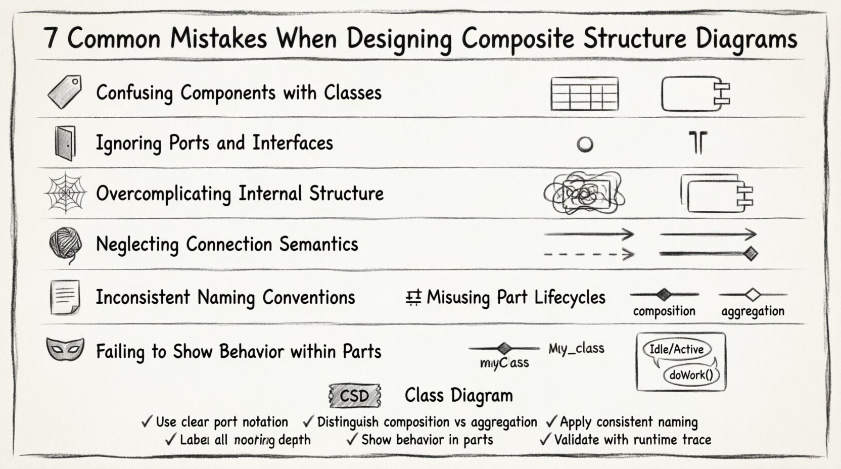
1. Confusing Components with Classes 🏷️
The most prevalent mistake involves treating composite parts simply as classes. While a component in a CSD is technically a classifier, its role is fundamentally different from a standard class in a class diagram.
- Classes represent data structures and logic within a single unit.
- Components represent modular units of implementation that may be deployed independently.
When you draw a part inside a composite structure, you are defining a physical or logical unit that has its own lifecycle and interface contract. If you define a part using only class attributes and methods without specifying ports or interfaces, you lose the structural context.
Why this matters:
- It obscures deployment boundaries.
- It hides interaction protocols.
- It leads to confusion during code generation.
Correction Strategy:
- Ensure every part represents a distinct unit of work.
- Verify that parts have defined interfaces for communication.
- Distinguish between the internal implementation details and the external contract.
2. Ignoring Ports and Interfaces 🚪
A composite structure diagram is essentially a blueprint for interaction. Without ports and interfaces, the internal wiring of a component is invisible.
Many designers draw connections directly between parts without defining the entry and exit points. This is technically incorrect in UML semantics. Connections must attach to ports, and ports must be typed by interfaces.
Common Errors:
- Connecting a part directly to another part.
- Using lines without arrowheads to indicate direction.
- Failing to specify whether an interface is provided (lollipop) or required (socket).
Impact on Architecture:
Without explicit ports, the diagram fails to show dependency management. It becomes impossible to determine which part depends on which service. This ambiguity causes coupling issues later in the software development lifecycle.
Best Practice:
- Always define a port for every interaction point.
- Specify the interface type on the port.
- Use provided and required interface stereotypes to show the flow of dependency.
3. Overcomplicating Internal Structure 🕸️
Detail is valuable, but excessive detail renders a diagram useless. A common error is attempting to document the entire internal logic of a component within a single composite structure diagram.
When a composite structure becomes too dense, readers cannot trace the flow of data or control. The purpose of the diagram is structural, not behavioral. If you find yourself adding state transitions or activity flows inside the parts, you are likely overstepping the scope of the CSD.
Signs of Overcomplication:
- More than 5-7 parts inside a single classifier.
- Dense text descriptions within part compartments.
- Multiple nested composite structures.
Correction Strategy:
- Break large components into sub-composites.
- Focus on the relationship between parts, not the internal code.
- Use separate diagrams for behavior (State Machine or Activity Diagrams).
4. Neglecting Connection Semantics 🧵
Connectors define how data flows between parts. However, the semantics of these connections are often glossed over. A simple line does not convey enough information about the type of association.
In a composite structure, you must distinguish between:
- Association: A structural relationship.
- Dependency: A usage relationship.
- Aggregation: A shared ownership relationship.
Table: Connector Types
| Connector Type | Meaning | Visual Indicator |
|---|---|---|
| Association | Parts are related structurally | Plain line |
| Dependency | One part uses another | Dashed arrow |
| Composition | Parts die with the whole | Filled diamond |
| Aggregation | Parts can exist independently | Hollow diamond |
Why Semantics Matter:
Incorrect connectors imply incorrect lifecycle management. If you use a composition diamond where an aggregation is needed, you imply that the part cannot exist without the composite. This restricts architectural flexibility.
5. Inconsistent Naming Conventions 📝
Readability depends on consistent terminology. A frequent oversight is mixing naming styles between the diagram and the codebase or other UML artifacts.
Common Inconsistencies:
- Using CamelCase for some parts and snake_case for others.
- Labeling parts by implementation class names instead of logical roles.
- Using abbreviations that are not defined elsewhere.
Impact on Collaboration:
When developers look at the diagram to understand the system, they expect to see terms they recognize. If the diagram says PaymentProcessor but the code has PayService, the mental translation required creates friction.
Standardization Rules:
- Adopt a strict naming convention for all parts.
- Ensure part names reflect their function, not their file name.
- Keep names consistent with the domain model.
6. Misusing Part Lifecycles (Composition vs Aggregation) ⚖️
The relationship between the composite and its parts dictates the lifecycle. A critical error occurs when designers confuse composition with aggregation.
Composition: The part has no meaning without the composite. If the composite is destroyed, the part is destroyed. Example: A House and its Door.
Aggregation: The part can exist independently. Example: A Team and its Members.
Why the Distinction is Critical:
- It affects memory management strategies.
- It influences database persistence logic.
- It defines error handling boundaries.
Correction:
Review the ownership rules for every part. Ask: “Can this part exist if the main composite is removed?” If the answer is yes, use aggregation. If no, use composition.
7. Failing to Show Behavior within Parts 🎭
A composite structure diagram focuses on structure, but it does not exist in a vacuum. Often, designers fail to link the structure to the behavior that drives it.
While you should not draw full activity flows inside the parts, you should indicate if a part has internal state or operations that affect the composite.
What to Include:
- Operations that are exposed to the composite.
- State changes relevant to the composite’s function.
- Signals passed between parts.
What to Exclude:
- Full sequence of method calls.
- Detailed algorithmic logic.
- External system interactions (unless relevant to the part).
Best Practice:
Use stereotypes or tags to denote if a part contains significant behavior logic. This signals to the reader that the part is not just a data container.
Comparison: Composite Structure vs Class Diagram 📊
To ensure clarity, it helps to understand when to use a Composite Structure Diagram versus a standard Class Diagram. They are not interchangeable.
| Feature | Composite Structure Diagram | Class Diagram |
|---|---|---|
| Focus | Internal structure of a classifier | Relationships between classes |
| Granularity | Parts, Ports, Connectors | Attributes, Methods, Associations |
| Deployment View | Can imply deployment | Logical view only |
| Complexity | High (for complex objects) | Medium (standard modeling) |
| Usage | Component-based architecture | Object-oriented design |
Validation Checklist ✅
Before finalizing your diagram, run through this validation list to catch common errors.
- Ports Defined: Do all external interactions have ports?
- Interfaces Typed: Are ports connected to specific interface definitions?
- Lifecycle Correct: Are composition and aggregation diamonds accurate?
- Scope Checked: Is the internal structure readable and not overcrowded?
- Names Consistent: Do part names match the domain model?
- Connectors Valid: Do lines represent valid relationships?
- Behavior Context: Are critical internal behaviors noted if necessary?
Final Considerations 🧭
Designing effective composite structure diagrams requires a balance between structural fidelity and readability. The goal is to communicate the internal organization of a system component clearly.
By avoiding the mistakes outlined above, you ensure that your diagrams serve as reliable references for developers and stakeholders. Precision in ports, interfaces, and relationships prevents ambiguity in the implementation phase.
Remember that a diagram is a tool for communication, not just a record of code. If the diagram cannot be understood by a new team member without explanation, it requires simplification. Focus on the structural relationships that define the system’s behavior and stability.
Adhering to these guidelines will result in documentation that stands the test of time, supporting the evolution of the architecture without requiring constant rewriting.