
Understanding complex system structures requires more than just looking at boxes and lines. When dealing with specialized modeling languages, the Profile Diagram becomes your essential tool for customizing standard notations to fit specific domain needs. This guide provides a structured approach to decoding these diagrams, ensuring you can extract meaningful architectural insights without getting lost in technical jargon.
What is a Profile Diagram? 🧩
A Profile Diagram is a specialized type of diagram used in modeling to define extensions for existing metamodels. Think of it as a template or a blueprint for adding new rules, icons, or behaviors to a standard modeling language. It allows architects to tailor the language to their specific project requirements without changing the underlying core rules.
In the context of software architecture, these diagrams are vital for:
- Domain Specificity: Creating notations that make sense to stakeholders in fields like embedded systems, finance, or healthcare.
- Standardization: Ensuring everyone on the team uses the same symbols for specific concepts.
- Clarity: Reducing ambiguity by explicitly defining how certain elements relate to one another.
When you see a profile diagram, you are not looking at the system itself, but rather the rules used to describe the system. It defines the vocabulary before the story is told.
Core Components of a Profile Diagram 🏗️
To interpret these diagrams correctly, you must recognize the fundamental building blocks. Unlike standard class diagrams, profile diagrams focus on the definitions of new elements. The following components are the most critical to identify:
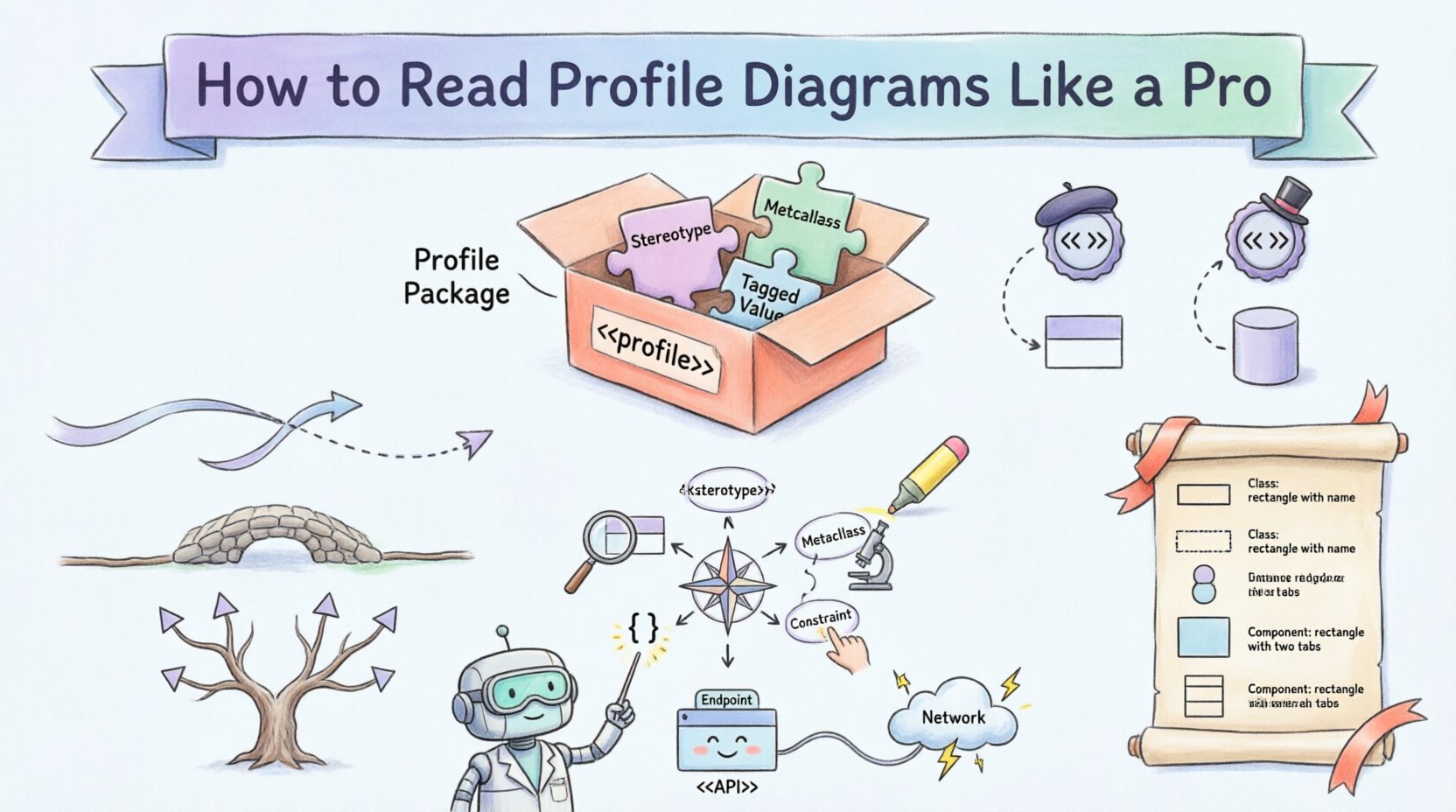
- Profile Package: This is the container for the profile. It holds the definitions of stereotypes and extensions. It is usually marked with the keyword <<profile>>.
- Stereotype: This is the core of customization. It is a mechanism to extend the vocabulary of the modeling language. It appears as a text string enclosed in guillemets, such as <<Entity>> or <<Service>>.
- Metaclass: This is the element from the base language that is being extended. For example, a standard Class or Component in the base model.
- Constraint: Rules or conditions that apply to the model elements when the stereotype is used. These are often written in text within braces { }.
- Tagged Value: Additional properties or data points associated with the stereotype. These allow for storing extra information like version numbers or priority levels.
Understanding Stereotypes and Extensions 🏷️
The stereotype is the most recognizable feature of a profile diagram. It acts as a label that modifies the meaning of a standard element. When reading a profile diagram, you need to understand the relationship between the stereotype and the base metaclass.
For instance, if you see a box labeled <<Database>>, it indicates that the box represents a standard Class element, but with specific properties defined by the database profile. These properties might include transaction support, data replication rules, or connection pooling settings.
When analyzing the extension mechanism, consider the following:
- Extension Points: Where in the base model can this stereotype be applied? Can it be applied to an Interface? A Component? A Class?
- Inheritance: Some stereotypes are derived from others. A <<SecureService>> might inherit from a base <<Service>> stereotype, adding security constraints on top.
- Constraints: What rules must be followed? If a stereotype requires a specific relationship, the diagram will show this constraint explicitly.
Reading Relationships and Dependencies 🔗
Relationships in a profile diagram define how the new elements interact with the base model. Interpreting these lines is crucial for understanding the flow of information and control.
Dependency
A dependency arrow indicates that one element requires another to function correctly. In a profile context, this often means a stereotype relies on a specific base class to be present in the model.
- Direction: The arrow points from the dependent element to the supplier.
- Usage: The dependent element cannot exist or function without the supplier.
Association
Association lines show a structural link between two classes. In profile diagrams, this might link a stereotype to a specific metaclass it extends.
- Role Names: Look for labels on the line that describe the nature of the relationship.
- Multiplicity: Numbers like 1, 0..1, or * indicate how many instances can be linked.
Generalization
This is the inheritance line. It shows that one stereotype is a specialized version of another. It is represented by a solid line with a hollow triangle arrowhead.
- Hierarchy: It creates a tree structure of stereotypes.
- Reusability: Sub-classes inherit properties from parent classes automatically.
A Step-by-Step Reading Guide 🧭
When you open a new profile diagram, do not try to understand everything at once. Follow this systematic approach to ensure accuracy.
Step 1: Identify the Package Structure
Locate the main profile package. This defines the scope of the customization. Note the name of the profile; this often matches the domain (e.g., "SecurityProfile" or "WebServicesProfile").
Step 2: Locate the Stereotypes
Find all elements marked with guillemets (<< >>). These are the custom elements you need to learn. Write them down or highlight them mentally.
Step 3: Analyze the Metaclasses
Check which standard elements are being extended. Are you extending Classes? Interfaces? Components? This tells you where you can apply the new notation in your actual models.
Step 4: Review Constraints and Tagged Values
Read the text blocks inside braces. These define the rules. If a stereotype requires a specific tagged value, you will know to provide that data when you use the element in a real diagram.
Step 5: Trace the Relationships
Follow the lines connecting the stereotypes to the metaclasses. This confirms the validity of the extension. Ensure there are no circular dependencies that might cause confusion.
Common Notation Rules and Tables 📊
To aid your interpretation, refer to these tables which summarize standard conventions used in profile diagrams.
Table 1: Basic Profile Elements
| Element | Visual Representation | Purpose |
|---|---|---|
| Profile Package | Box with <<profile>> label | Container for profile definitions |
| Stereotype | Text in << >> above element | Extends vocabulary of base language |
| Metaclass | Standard UML shape (e.g., Class) | The base element being extended |
| Constraint | Text in { } braces | Rules or conditions for the element |
| Tagged Value | Text in { name = value } | Additional properties for the stereotype |
Table 2: Relationship Types
| Relationship | Line Style | Arrowhead | Meaning |
|---|---|---|---|
| Dependency | Dashed Line | Open Arrow | One element uses another |
| Association | Solid Line | None or Open Arrow | Structural link between elements |
| Generalization | Solid Line | Hollow Triangle | Inheritance or specialization |
| Realization | Dashed Line | Hollow Triangle | Implementation of an interface |
Practical Example: A Web Service Profile 🌐
Imagine a team building a distributed web application. They need to distinguish between internal data stores and external APIs. They create a Web Service Profile.
In this profile, they define a stereotype <<API>> that extends the standard Component. They add a tagged value called "Endpoint" and a constraint that requires the component to have a dependency on a "Network" element.
When reading the diagram:
- Identify the Component: You see a box with the label <<API>>.
- Check the Tagged Value: You look for "Endpoint" to see the URL path.
- Check the Constraint: You verify there is a dashed line connecting it to a Network element.
This confirms the component is an API designed for external communication, not an internal utility.
Integrating with Other Diagrams 🔄
Profile diagrams do not exist in isolation. They are meant to enhance other types of diagrams. Understanding how they integrate is key to holistic system design.
With Class Diagrams
When you apply a profile to a Class Diagram, the stereotypes become visible on the class boxes. This immediately tells you the domain role of that class without needing a legend.
With Component Diagrams
Profiles help define the interfaces and provided/required capabilities of components. A <<Service>> stereotype might imply that the component provides a specific set of operations defined in the profile.
With Deployment Diagrams
Profiles can define the type of node required. For example, a <<DatabaseNode>> stereotype might indicate that a node requires specific storage configurations or high availability settings.
Troubleshooting Interpretation Issues 🛠️
Even with a good guide, confusion can arise. Here are common pitfalls and how to resolve them.
- Missing Stereotype: If you see a box but no stereotype label, check the profile package. It might be a standard element without customization.
- Ambiguous Lines: If a line style is unclear, look for the legend. Some tools allow customization of line styles, which can deviate from standard rules.
- Complex Inheritance: If a stereotype inherits from multiple parents, ensure you understand which properties come from which source. Trace the lines back to the root.
- Hidden Constraints: Sometimes constraints are stored in metadata rather than visible text. Check the properties panel of the element if available.
Best Practices for Modeling with Profiles ✅
To ensure your diagrams remain readable and useful over time, adhere to these guidelines.
- Keep it Simple: Do not create too many stereotypes. If a concept is complex enough to need a new profile, it might be a sign to refactor the domain model.
- Document Thoroughly: Every stereotype should have a clear description. Do not rely on memory. Write down what each tag means.
- Consistent Naming: Use consistent naming conventions for stereotypes. If you use <<Service>, do not switch to <<Serv> halfway through.
- Review Regularly: Profiles evolve. As the project grows, revisit the profile diagram to ensure it still matches the current system architecture.
- Align with Standards: Ensure your profile extensions do not conflict with industry standards unless there is a compelling reason not to.
The Value of Precision in Architecture 🎯
Using profile diagrams correctly leads to better communication between stakeholders. When developers, architects, and testers all understand the same notation, errors decrease, and development speed increases.
By mastering the reading of these diagrams, you gain the ability to quickly assess the architectural intent of a system. You can spot potential issues, such as missing dependencies or incorrect data flows, before implementation begins.
This skill transforms you from a passive viewer of diagrams into an active interpreter of system design. It allows you to validate the model against the requirements and ensure that the technical implementation matches the business goals.
Summary of Key Takeaways 📝
- Profile Diagrams define extensions for standard modeling languages.
- Stereotypes are the primary mechanism for adding new vocabulary.
- Metaclasses define where these stereotypes can be applied.
- Relationships show how the new elements connect to the base model.
- Constraints and Tagged Values add specific rules and data.
- Integration with other diagrams makes the profile useful in practice.
- Consistency in naming and documentation is essential for maintainability.
By following the steps outlined in this guide, you can navigate profile diagrams with confidence. You will be able to read the technical specifications and understand the underlying structure of the system you are analyzing. This proficiency is a hallmark of experienced system architects who prioritize clarity and precision in their documentation.