


Designing complex systems requires more than just functional specifications. It demands a clear understanding of how individual parts interact to form a cohesive whole. The Composite Structure Diagram (CSD) serves as a critical tool in this endeavor, offering a granular view of internal system composition. When executed with precision, this visualization method clarifies dependencies, defines boundaries, and ensures architectural integrity. This guide provides a comprehensive walkthrough on how to construct these diagrams effectively, focusing on structure, relationships, and clarity.
📐 Understanding the Fundamentals of Composite Structures
Before drawing any lines or boxes, it is essential to grasp the theoretical underpinnings of composite structure modeling. Unlike a Class Diagram, which focuses on static attributes and methods, a Composite Structure Diagram emphasizes the physical and logical arrangement of components. It answers the question: “How is this system built from the inside out?”
A composite structure diagram typically consists of the following core elements:
- Composite Structure: The container or the system boundary being analyzed.
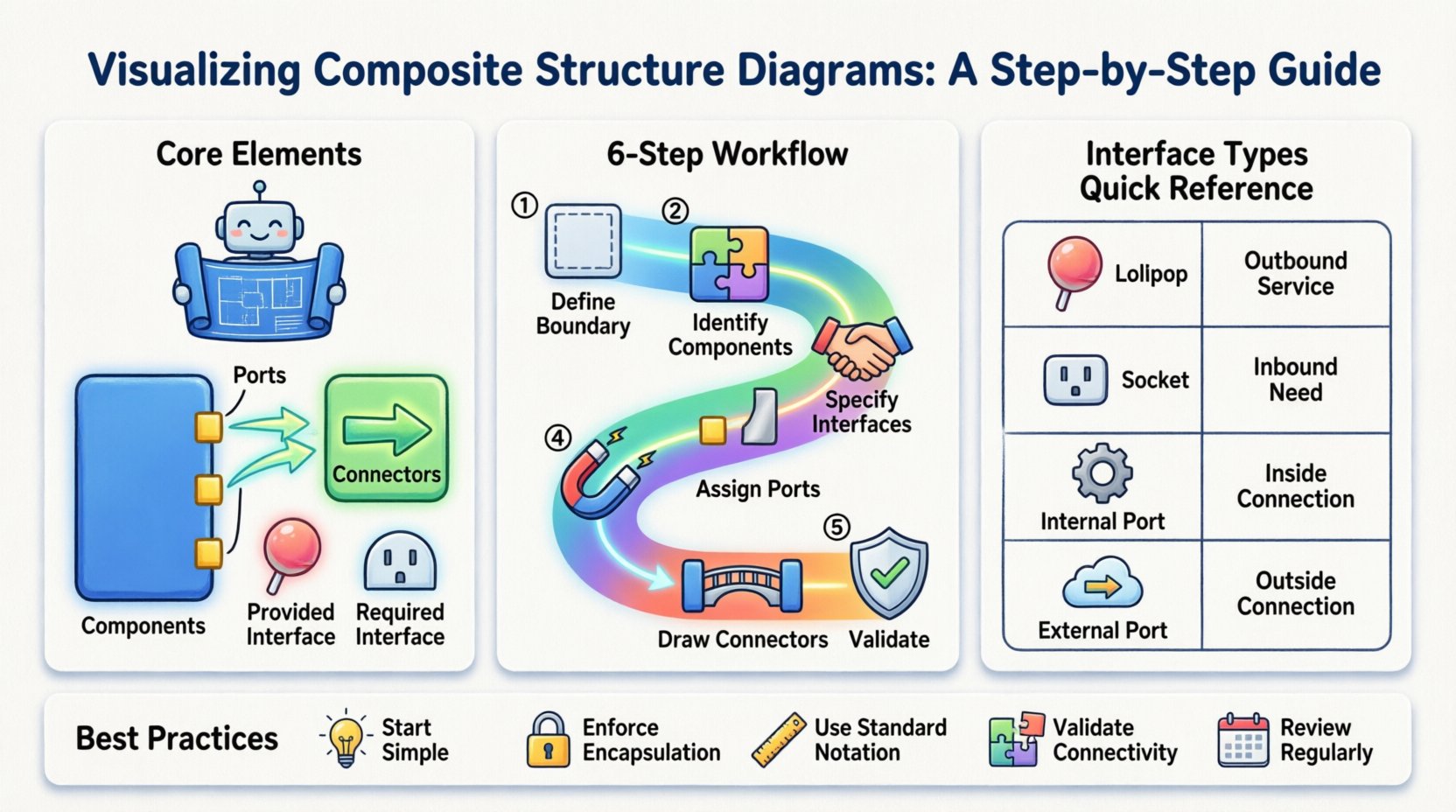
- Parts: The constituent components within the structure.
- Connectors: The links that allow data or control flow between parts.
- Interfaces: The contracts defining how parts interact with the outside world or each other.
- Ports: Specific connection points on a component.
Visualizing these elements correctly prevents ambiguity during the implementation phase. It ensures that developers understand not just what the system does, but how it is assembled. This level of detail is particularly vital in distributed systems, hardware-software integration, and complex enterprise architectures.
🛠️ Core Elements and Their Definitions
To maintain accuracy, every element within your diagram must adhere to standard modeling conventions. Below is a breakdown of the specific roles each element plays in the composite structure.
1. Components as Building Blocks
A component represents a modular unit of functionality. In a composite structure context, a component is often a subsystem itself, containing its own internal logic. When modeling, treat components as black boxes from the outside, but as transparent units when defining the internal structure of the composite.
2. Ports: The Connection Points
Ports define where a component connects to the rest of the system. They are the entry and exit points for communication. It is crucial to distinguish between:
- Provided Interfaces: Capabilities offered by the component.
- Required Interfaces: Capabilities needed by the component to function.
3. Connectors and Links
Connectors establish the communication paths between ports. They do not merely link boxes; they represent the actual data flow or control signals. In a well-structured diagram, the type of connector often implies the protocol or mechanism used for interaction.
📋 Comparative View of Interface Types
Understanding the distinction between interface types is fundamental to accurate modeling. Use the following table to guide your interface selection during the design process.
| Interface Type | Direction | Function | Visual Representation |
|---|---|---|---|
| Provided (Lollipop) | Outbound | Service offered to others | Circle attached to port |
| Required (Socket) | Inbound | Service needed by component | Half-circle attached to port |
| Internal Port | Internal | Links parts within the same composite | Small square on the edge |
| External Port | External | Connects to outside system | Port on system boundary |
🚀 Step-by-Step Modeling Workflow
Constructing a valid composite structure diagram follows a logical progression. Rushing through steps often leads to missing dependencies or incorrect interface mappings. Follow this structured approach to ensure robustness.
Step 1: Define the System Boundary
Begin by establishing the scope. What exactly is being modeled? Is it a single microservice, a hardware module, or the entire enterprise application? Draw a large rectangle to represent the composite structure. Label this clearly with the system name. This boundary separates internal logic from external interactions.
Step 2: Identify Internal Components
Break the system down into its constituent parts. List every component that resides inside the boundary. These might be sub-systems, libraries, or hardware units. Place each component as a rectangle inside the main boundary. Ensure that no component exists outside this boundary unless it is an external dependency.
Step 3: Specify Interfaces and Contracts
For each component, determine what it needs and what it provides. This step is often overlooked but is critical for integration. If Component A requires a database, it must have a required interface for the database connection. If Component B processes data, it should provide an interface for that processing. Document these explicitly.
Step 4: Assign Ports to Components
Ports are the physical locations where interfaces are implemented. Place a small square or circle on the edge of each component rectangle. Attach the interfaces defined in the previous step to these ports. This visualizes the physical contact points between software modules or hardware parts.
Step 5: Draw the Connectors
Now, link the ports together. Use lines to connect required interfaces to provided interfaces. Ensure that the directionality makes sense. A data flow should go from a source to a destination. If a component requires a service and another provides it, draw a line connecting their respective ports. Avoid crossing lines where possible to maintain readability.
Step 6: Validate Relationships and Constraints
Review the connections. Are all required interfaces satisfied? Are there any dangling ports that imply missing functionality? Check for circular dependencies, where Component A needs B, and B needs A directly within the same composite. While sometimes necessary, these should be clearly marked. Ensure that the internal structure supports the external contract defined for the composite.
🔧 Advanced Modeling Techniques
As systems grow in complexity, basic diagrams may become insufficient. Advanced techniques allow for deeper analysis and better documentation.
Delegation Connectors
Delegation allows a composite structure to forward requests to a specific internal part. Instead of connecting an external port directly to a final component, you connect it to an intermediate part which then handles the request. This reduces clutter and encapsulates internal routing logic. Use delegation connectors to show that the composite handles the complexity of routing internally.
Internal Collaborations
Use internal collaboration rectangles to group related parts. If multiple components work together to form a specific feature, encapsulate them in a collaboration box. This clarifies that their interaction is specialized and distinct from the rest of the system. It helps in managing complexity by grouping logical units.
Nesting Structures
Complex systems often have nested structures. A component might itself be a composite structure containing further sub-components. When modeling this, ensure the nesting is clear. You can represent a composite component by drawing its own internal structure diagram inside the parent diagram, or by using a collapsed view in your modeling tool. Consistency is key to maintaining readability.
⚠️ Common Errors and How to Avoid Them
Even experienced architects make mistakes when visualizing composite structures. Being aware of common pitfalls helps maintain diagram quality.
- Over-complication: Trying to show every single method call or variable. Keep the focus on structure and connectivity, not implementation details.
- Missing Interfaces: Drawing connections without defining the interface they use. Every connector should ideally reference a specific interface definition.
- Unclear Boundaries: Allowing parts to drift outside the composite box without clear context. Ensure all internal parts are strictly contained.
- Disconnected Ports: Leaving ports without connections. Every provided interface should ideally be consumed by something, or explicitly marked as unused if that is the design intent.
- Inconsistent Naming: Using different names for the same component across different diagrams. Maintain a strict naming convention to avoid confusion.
🔗 Integration with Other Architectural Views
A composite structure diagram does not exist in isolation. It is part of a larger ecosystem of diagrams that describe the system. Integrating it with other views ensures a holistic understanding.
Relation to Class Diagrams
While Class Diagrams show static relationships between classes, Composite Structure Diagrams show how those classes are grouped into deployable or executable units. Use the Class Diagram to define the internal behavior, and the Composite Structure Diagram to define the physical deployment of those classes.
Relation to Deployment Diagrams
Deployment diagrams show where components run (nodes, servers). Composite Structure Diagrams show what components are inside a node. A single node in a deployment diagram might contain multiple composite structures. Align the boundaries of your composite structures with the physical nodes where possible.
Relation to Sequence Diagrams
Sequence diagrams show the flow of messages over time. Composite Structure Diagrams show the static path those messages take. Use the Composite Structure to verify that the paths in your sequence diagrams are physically possible. If a sequence diagram shows a message going from Component A to Component B, ensure a connector exists between them in the composite view.
🛡️ Maintenance and Evolution of the Model
Systems evolve. New features are added, and old components are deprecated. The composite structure diagram must be treated as a living document. Regular maintenance ensures the diagram remains a useful tool rather than a historical artifact.
Version Control: Treat your diagrams with the same version control discipline as code. Tag changes when major architectural shifts occur. This allows you to trace how the structure has changed over time.
Refactoring Triggers: If the diagram becomes too dense, it is a signal to refactor the architecture. If you find yourself adding many delegation connectors to bypass complexity, consider splitting the composite into smaller, more manageable structures.
Documentation Consistency: Ensure that any changes to the diagram are reflected in the technical documentation. If a component is removed from the diagram, the API documentation should be updated accordingly. Discrepancies between the model and the code lead to confusion and technical debt.
📊 Benefits of Precise Visualization
Investing time in accurate composite structure modeling yields tangible benefits throughout the project lifecycle.
- Reduced Integration Issues: By clearly defining ports and interfaces, developers know exactly how to plug components together, reducing runtime errors.
- Clearer Communication: Stakeholders and developers can agree on the system layout without ambiguity. Visuals bridge the gap between technical and non-technical teams.
- Easier Debugging: When a failure occurs, the diagram provides a map to trace the path of data flow, helping isolate the faulty component quickly.
- Scalability Planning: Understanding the internal structure allows architects to plan for scaling specific components independently without affecting the whole system.
🧩 Summary of Best Practices
To ensure your composite structure diagrams serve their purpose effectively, adhere to the following checklist during your design sessions.
- Start Simple: Define the outer boundary and major components before adding internal details.
- Enforce Encapsulation: Ensure internal ports are not exposed directly to the outside unless necessary.
- Use Standard Notation: Stick to standard UML shapes for components and ports to maintain industry standard compliance.
- Validate Connectivity: Check that every required interface has a matching provider within the scope.
- Review Regularly: Schedule periodic reviews of the diagram to ensure it matches the current codebase state.
By following these guidelines, you create a reliable blueprint for system construction. The effort invested in modeling pays dividends in clarity, maintainability, and architectural stability. Remember, the goal is not just to draw a picture, but to define a clear path for implementation.
🔍 Final Considerations for Implementation
When moving from the diagram to the codebase, ensure that the structural definitions map directly to the file structure or module organization. If your composite structure diagram specifies three distinct parts, your codebase should ideally reflect three distinct modules or libraries. This alignment minimizes the gap between design and execution.
Additionally, consider the performance implications of your connections. Heavy data flows between tightly coupled components might require optimization, such as caching or asynchronous processing. The composite structure diagram provides the context to make these architectural decisions informed by the physical layout of the system.
Finally, keep the diagram accessible. Store it in a central repository where all team members can view and reference it. A diagram that is hidden or outdated fails its primary purpose of communication. Regular updates and clear accessibility ensure the model remains a trusted source of truth for the entire development team.