


Designing complex software systems requires precision. When you rely on intuition rather than defined structure, the resulting architecture often fails under pressure. The Composite Structure Diagram (CSD) is a specialized UML artifact designed to reveal the internal organization of a classifier. It details how parts interact through connectors, ports, and interfaces. Without a validated structure, the system remains a guess.
This guide moves beyond basic definitions. It offers a granular checklist to ensure every element in your diagram serves a functional purpose. We will examine parts, roles, ports, and connections in depth. By following these steps, you ensure that your model accurately reflects the implementation reality.
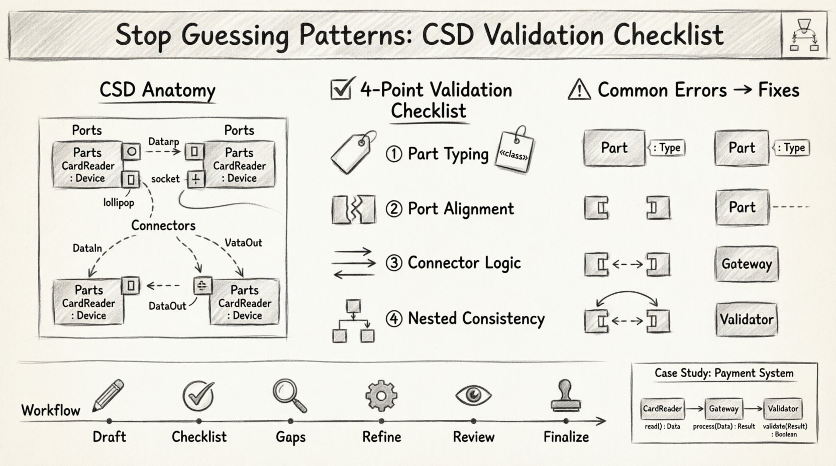
🏗️ Understanding the Anatomy of a Composite Structure Diagram
Before validating, one must understand the components. A Composite Structure Diagram is not just a collection of boxes. It is a map of internal interactions. Every line drawn must represent a flow of data or control. Every box must represent a deployable or logical unit.
📦 Parts and Internal Nodes
Parts are the fundamental building blocks. They represent instances of classifiers within the composite structure. Unlike simple association links, parts have a specific lifecycle managed by the composite object. They are not merely connected; they are contained.
- Part Definition: Every part must have a defined type. A part cannot exist as a generic blob.
- Ownership: The composite classifier owns the part. If the composite is destroyed, the part lifecycle ends unless specified otherwise.
- Visibility: Parts can be public, private, or protected. This dictates accessibility from outside the composite.
🔌 Ports and Roles
Ports are the interaction points of a part. They define where the part connects to the outside world or to other internal parts. Roles define how the part participates in a connection.
- Provided Interfaces: A port can offer services. This is often shown as a lollipop notation.
- Required Interfaces: A port can demand services. This is often shown as a slot notation.
- Role Names: Every connection point should have a role name to clarify the relationship.
🔗 Connectors and Bindings
Connectors link ports together. They represent the flow of communication. Bindings connect a port to a role. These are the physical or logical wires of your architecture.
- Connector Type: Is this a data flow, a signal, or a control message?
- Directionality: Ensure the arrow direction matches the intended data flow.
- Multiplicity: Can one port connect to many, or just one?
✅ The Validation Checklist: Ensuring Structural Integrity
Validation is the process of checking your work against established rules. It prevents ambiguity. Use this checklist during the design phase and before handing off specifications.
1. Part Definition and Typing
Ensure every internal component is fully typed. An untyped part is a black box that cannot be tested or implemented correctly.
- Check: Does every part have a specific class or interface type?
- Check: Are the types reusable elsewhere in the model?
- Check: Is the multiplicity of the part defined (e.g., 1, 0..1, *)?
- Check: Are parts nested correctly within their parent composite?
2. Port Interface Alignment
Ports must match the interfaces they expose or require. Mismatches here lead to runtime errors.
- Check: Does a provided port have a valid provided interface defined?
- Check: Does a required port have a valid required interface defined?
- Check: Are the method signatures on the interface compatible?
- Check: Are the ports visible to the connectors they intend to use?
3. Connector Logic and Binding
Connectors define the relationship. They must be logically sound.
- Check: Do both ends of the connector have a valid port?
- Check: Is the direction of the connector consistent with the interface contract?
- Check: Are there any dangling connectors that do not attach to a port?
- Check: Are there circular dependencies that could cause deadlock?
4. Nested Structure Consistency
Composite structures often nest. A part can contain its own parts. This hierarchy must be clear.
- Check: Are nested parts clearly grouped within a boundary?
- Check: Does the nesting imply ownership or merely containment?
- Check: Are interfaces exposed at the correct level (internal vs. external)?
- Check: Is the depth of nesting manageable for the reader?
📊 Common Errors and Corrections
Reviewing the table below will help identify common pitfalls in Composite Structure Diagrams. These are frequent mistakes that invalidate the diagram.
| Issue | Impact | Correction |
|---|---|---|
| Untyped Parts | Implementation ambiguity | Assign a specific class type to every part. |
| Disconnected Ports | Dead code in design | Remove unused ports or connect them to valid roles. |
| Interface Mismatch | Runtime failure | Ensure provided and required interfaces match signatures. |
| Unclear Multiplicity | Memory leaks or errors | Define 1, 0..1, or * explicitly on all parts. |
| Circular Ports | Deadlock risk | Break cycles by introducing intermediate components. |
| Missing Roles | Confusion in usage | Add role names to all connector ends. |
🔌 Deep Dive: Interfaces and Roles
Interfaces are the contracts that parts fulfill. In a Composite Structure Diagram, they are critical. They define the boundary between the internal implementation and external usage.
Provided vs. Required
Understanding the difference is vital for validation. A part can provide functionality that another part requires. This is the service-oriented view of the composite.
- Provided Interface: The part offers this service. It is a capability.
- Required Interface: The part needs this service to function. It is a dependency.
- Binding: The connection between a required port and a provided port.
Role Names
Never leave a connector without a role name. A connector without a role name is a wire with no label. It tells the developer nothing about the nature of the traffic.
- Example: Instead of a line, use “DataIn” and “DataOut”.
- Clarity: Role names should be verbs or clear nouns.
- Consistency: Use the same role name if the same connection type is used elsewhere.
🔒 Encapsulation and Visibility
Encapsulation is a core principle. The internal structure should be hidden unless exposed via ports. Validation involves checking visibility modifiers.
- Public Parts: Accessible from outside the composite. Use sparingly.
- Private Parts: Accessible only within the composite. Default setting for safety.
- Protected Parts: Accessible within the composite and subclasses.
- Internal Nodes: These are the containers for the parts. Ensure they are not exposed directly.
📏 Scaling and Maintenance
As the system grows, the diagram grows. A valid diagram today must remain valid tomorrow. Consider these factors for long-term maintenance.
Decomposition
If a composite structure becomes too large, decompose it. Do not put all parts in one diagram. Create sub-composites.
- Threshold: If the diagram exceeds one screen, split it.
- Boundaries: Clearly mark where the boundary of a sub-composite begins.
- References: Use references to other diagrams to maintain context.
Version Control
Changes to the structure must be tracked. Every change to a part or connector affects the system behavior.
- Log Changes: Document why a part was added or removed.
- Impact Analysis: Before changing a port, check all dependent connectors.
- Backward Compatibility: Ensure new interfaces do not break existing consumers.
🧩 Integration with Other Diagrams
A Composite Structure Diagram does not exist in isolation. It must align with Class Diagrams, Sequence Diagrams, and Deployment Diagrams.
Alignment with Class Diagrams
The parts in your CSD must exist in your Class Diagram. Every part type should have a corresponding class definition.
- Consistency: Verify that attributes and methods match.
- Realization: Ensure classes realize the interfaces shown in the CSD.
Alignment with Sequence Diagrams
Sequence diagrams show the flow of messages. CSD shows the structure that supports that flow. They must agree.
- Message Flow: Does the message in the sequence diagram correspond to a connector in the CSD?
- Part Existence: Are all participants in the sequence diagram present in the CSD?
Alignment with Deployment Diagrams
Deployment diagrams show where software runs. CSD shows what software is inside. They must match.
- Deployment: Can the parts be deployed to the nodes shown in the deployment diagram?
- Dependencies: Do the runtime dependencies match the structural dependencies?
🛠️ Practical Application of the Checklist
How do you apply this in a real project? Follow this workflow.
- Draft the Diagram: Create the initial structure based on requirements.
- Run the Checklist: Go through each item in the validation list.
- Identify Gaps: Note any missing types, ports, or connectors.
- Refine: Update the diagram to close the gaps.
- <Peer Review: Have a colleague review the diagram using the same checklist.
- Finalize: Mark the diagram as validated and baselined.
🔍 Case Study: A Payment System Component
Consider a Payment Processor. It needs a Card Reader, a Gateway, and a Validator.
- Card Reader: Requires a connection to the Gateway. Provides data.
- Gateway: Requires connection to Validator. Provides transaction status.
- Validator: Provides validation service. Requires connection to Gateway.
Validation Check:
- Are all parts typed? Yes (CardReader, Gateway, Validator).
- Are ports defined? Yes (DataIn, DataOut, Status).
- Are interfaces matched? Yes (Gateway provides Status, Validator requires Status).
- Are connectors clear? Yes (Lines labeled with interface names).
If any of these were missing, the system would be invalid. This logic applies to all domains.
📝 Final Thoughts on Diagram Validity
Validity is not a one-time check. It is a continuous process. As requirements change, the structure must adapt. The checklist ensures that the adaptation remains sound. By adhering to these standards, you build a model that is not just a drawing, but a blueprint for engineering success.
Remember, the goal is clarity. If a stakeholder cannot understand the diagram, it has failed. Use the checklist to enforce that clarity. Ensure every part, port, and connector has a reason to exist. This discipline separates functional architecture from speculative design.
Start applying this checklist to your next model. Verify the types. Check the interfaces. Validate the connections. Your system will thank you for the rigor.