


Understanding the internal architecture of a system requires more than just a list of classes or a high-level component view. When developers need to see how objects interact internally, how responsibilities are distributed among parts, and how those parts connect to the outside world, the Composite Structure Diagram becomes essential. This guide addresses the most intricate questions surrounding this UML artifact, providing clear, technical answers without relying on specific tooling.
Composite Structure Diagrams reveal the internal structure of a classifier. They show how a classifier is composed of parts, how these parts are connected, and how they communicate through interfaces. This level of detail is crucial for complex software engineering, embedded systems, and architecture design where the internal logic matters as much as the external interface.
🏗️ Understanding the Core Components
Before diving into specific questions, it is vital to establish a strong foundation regarding the elements that make up a Composite Structure Diagram. Each element serves a specific semantic purpose within the Unified Modeling Language (UML) specification.
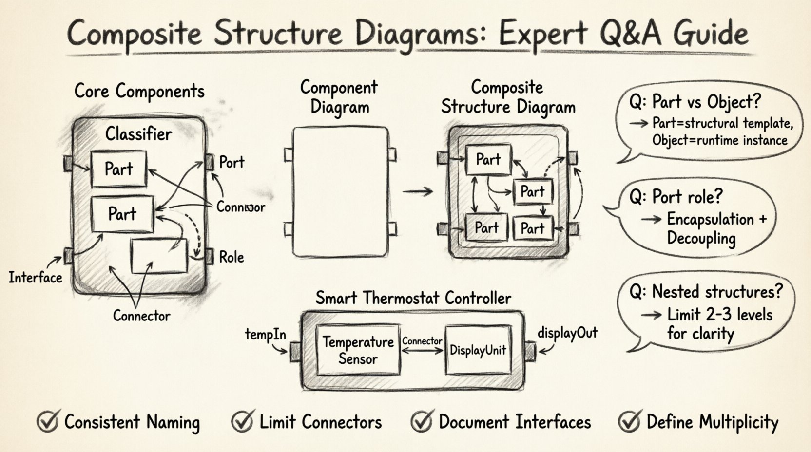
- Classifiers: The container for the internal structure. This is typically a Class, Component, or Node.
- Parts: Instances of classifiers that make up the composite structure. They represent the components residing inside the classifier.
- Ports: Interaction points on a part. Ports define where a part connects to the outside world or to other internal parts.
- Interfaces: Contracts that define a set of operations. Parts provide interfaces, and other parts require them.
- Connectors: Links that establish communication paths between ports. They define the flow of data or control.
- Roles: Names assigned to the ends of connectors to clarify the direction of interaction.
Visualizing these elements helps clarify the architecture. A part does not just exist; it has a type, a name, and a state. It interacts with the rest of the system through defined boundaries.
❓ Q&A: Addressing Complex Modeling Scenarios
Q1: How does a Composite Structure Diagram differ from a Component Diagram?
This is the most frequent source of confusion for modelers. Both diagrams deal with parts and components, but their scope and purpose differ significantly.
- Component Diagram: Focuses on the external view. It shows how different components interact at a system level. It does not typically show the internal wiring of a component.
- Composite Structure Diagram: Focuses on the internal view. It reveals the anatomy of a single classifier. It details how the internal parts are arranged and connected.
If you need to show how the “Billing Module” talks to the “User Module,” you use a Component Diagram. If you need to show how the “Billing Module” is built internally using a “Validator,” a “Formatter,” and a “Logger,” you use a Composite Structure Diagram.
Q2: When should I use a Part versus an Object?
In UML, the distinction lies in the static nature of the definition versus the dynamic nature of the instance.
- Part: Represents a structural component defined at the class level. It is a template for how the internal structure is organized. It has a type (a class) and multiplicity.
- Object: Represents a specific instance at runtime. While parts imply the existence of objects, the diagram itself defines the structure, not the specific runtime state.
Using parts allows you to define a reusable internal pattern. You can instantiate this pattern multiple times across different parts of your system without redefining the internal connections every time.
Q3: What is the role of a Port in a Composite Structure?
Ports are the gatekeepers of interaction. They encapsulate the interface logic.
- Encapsulation: A part can have many operations, but only the ones exposed through a port are visible to the outside.
- Decoupling: By using ports, the internal implementation of a part can change without affecting the parts connected to it, as long as the interface contract remains the same.
- Directionality: Ports can be provided (offering services) or required (consuming services).
Consider a database engine. It provides a connection port for clients to send SQL queries. It requires a storage port to write data. These distinct roles help manage complexity and ensure data flows correctly.
📊 Comparison: Internal Structure Elements
To clarify the nuances between different structural elements, refer to the following comparison table.
| Element | Primary Function | Visibility | Example Use Case |
|---|---|---|---|
| Part | Defines a component within the structure | Internal to Classifier | A “Processor” part inside a “Computer” class |
| Port | Interaction point for connections | Boundary of Part | A “Network Port” allowing data entry |
| Connector | Links two ports together | Internal Path | The wire connecting a CPU to RAM |
| Interface | Contract of operations | Defined at Port | An “I/O Interface” for data transfer |
🧐 Q&A: Navigating Technical Challenges
Q4: How do I handle nested composite structures?
Nesting is a powerful feature that allows for hierarchical modeling. You can place a composite structure inside a part of another composite structure.
- Clarity: Deep nesting can make diagrams hard to read. Limit nesting to two or three levels to maintain readability.
- Abstraction: Use nesting when the internal structure of a part is too complex to ignore, but you do not want to create a separate diagram for it.
- Reuse: If a sub-structure is used in multiple places, consider defining it as a separate classifier and referencing it as a part type.
For example, a “Vehicle” class might contain a “Engine” part. The “Engine” part might have its own internal composite structure showing the “Piston” and “Cylinder” parts. This keeps the high-level view clean while allowing deep dives when necessary.
Q5: Can a part have multiple ports?
Yes, a single part can have multiple ports. This is common in complex systems where a component must interact with various subsystems.
- Separation of Concerns: One port might handle input, while another handles output. A third might handle configuration.
- Interface Types: Each port can require or provide different interfaces. A part might require a “Logging Interface” on one port and provide a “Data Access Interface” on another.
This modularity ensures that the internal logic remains organized. Changes to the logging mechanism do not necessitate changes to the data access mechanism, provided the interfaces remain stable.
Q6: How are state changes represented in Composite Structure?
Composite Structure Diagrams focus on static structure, not dynamic behavior. They do not explicitly show state transitions like a State Machine Diagram does.
- Structure vs Behavior: If you need to show how a part behaves during a state change, use a State Machine Diagram attached to the class.
- Constraints: You can use notes or constraints within the Composite Structure Diagram to indicate that certain parts must be in a specific state before a connection is valid.
Maintaining the separation of structural and behavioral diagrams keeps the model clean. The Composite Structure Diagram answers “What is it made of?” while the State Machine Diagram answers “How does it behave?”
📏 Best Practices for Modeling
Creating effective diagrams requires adherence to specific guidelines to ensure the model remains maintainable and understandable over time.
- Consistent Naming: Use clear, descriptive names for parts and ports. Avoid generic names like “Part1” or “PortA” unless there is a strong technical reason.
- Limit Connector Length: Avoid crossing connectors. Use orthogonal routing to keep the diagram organized.
- Document Interfaces: Always define the interface explicitly at the port. Do not assume the operations are known.
- Maintain Multiplicity: Clearly define the multiplicity of parts. Is there one part, many parts, or an optional part?
- Use Stereotypes: If your modeling environment supports it, use stereotypes to indicate specific types of parts (e.g., <<device>>, <<service>>).
🛠️ Real-World Application Examples
Applying these concepts to real-world scenarios solidifies understanding. Consider the following examples.
Example 1: Embedded Control System
In an embedded system for a smart thermostat, the main controller class might be modeled using a Composite Structure Diagram.
- The Controller has a part called TemperatureSensor.
- The TemperatureSensor has a port that provides a AnalogRead interface.
- The Controller has a part called DisplayUnit.
- A Connector links the sensor’s output port to the controller’s input port.
This diagram clarifies the data flow from the physical sensor to the processing unit without needing to write code.
Example 2: Enterprise Software Module
In a large enterprise application, a OrderProcessingModule might be decomposed.
- It contains a ValidationService part.
- It contains a PricingEngine part.
- It contains a NotificationService part.
- The OrderProcessingModule exposes a ProcessOrder port.
- Internally, this port connects to the PricingEngine to calculate costs and the ValidationService to check data integrity.
This structure allows developers to swap out the PricingEngine for a different implementation without breaking the external interface of the module.
🔁 Maintenance and Evolution
Models are not static documents; they evolve as the system does. Keeping Composite Structure Diagrams up to date is critical.
- Review Cycles: Integrate diagram reviews into the sprint cycle. If code changes affect the internal structure, update the diagram.
- Version Control: Treat diagram files like code. Use version control systems to track changes in structure over time.
- Impact Analysis: When a part is removed or modified, use the diagram to identify which connectors and ports are affected.
Ignoring structural updates leads to a drift between the model and the implementation. This drift reduces trust in the documentation and makes onboarding new developers more difficult.
📉 Common Pitfalls to Avoid
Avoiding common mistakes ensures the quality of your modeling effort.
- Over-Engineering: Do not model every internal detail for every class. Focus on classes where the internal structure is complex or critical to the architecture.
- Mixing Concerns: Do not mix behavioral logic into the structural diagram. Keep the diagram focused on composition and connection.
- Ignoring Multiplicity: Failing to specify how many instances of a part exist can lead to misunderstandings about memory or resource usage.
- Redundant Interfaces: Do not create new interfaces for every single operation. Group related operations into cohesive interfaces.
🔍 Deep Dive: Ports and Roles
Ports and roles are often the most misunderstood elements. Understanding the relationship between them is key to accurate modeling.
- Port: The location where interaction happens. It has a type (interface) and visibility.
- Role: The name of the interaction at the end of a connector. It describes the function of the connection from the perspective of the part.
For instance, a Printer part might have a port that provides a PrintJob interface. A Document part might have a port that requires a PrintJob interface. The connector between them might have roles named sender and receiver.
This distinction allows for flexibility. The same interface can be used in different contexts with different role names, clarifying the intent of the connection without changing the underlying contract.
🎯 Summary of Key Takeaways
Composite Structure Diagrams provide a necessary lens for understanding internal system architecture. They bridge the gap between high-level component views and low-level code implementation.
- Focus on Internal Structure: Use them to show parts, ports, and connectors within a classifier.
- Separate from Behavior: Keep structural and behavioral diagrams distinct.
- Use Interfaces: Define clear contracts at ports to ensure decoupling.
- Maintain Consistency: Ensure the diagram reflects the actual implementation.
By mastering the application of these diagrams, teams can achieve better architectural clarity, reduce integration errors, and facilitate more effective communication among stakeholders. The effort invested in accurate modeling pays dividends during the maintenance and scaling phases of the software lifecycle.
🚀 Next Steps for Modelers
Start by identifying the most complex classes in your system. Draft a Composite Structure Diagram for one of them. Focus on defining the parts and their connections. Review the diagram with the development team to ensure it matches their understanding of the code. Iterate based on feedback.
As you gain experience, you will find that the Composite Structure Diagram becomes a natural tool for thinking about system design. It forces you to consider how components fit together, how data flows, and where responsibilities lie. This clarity is the foundation of robust software engineering.