


When diving into the depths of Unified Modeling Language (UML), few diagrams spark as much confusion as the Composite Structure Diagram. Often overshadowed by the ubiquity of Class Diagrams and Sequence Diagrams, this visual notation holds critical power for understanding internal system organization. However, a persistent fog of misunderstanding surrounds its utility and application. Senior Solution Architects frequently encounter teams skipping this modeling step, leading to brittle codebases and unclear component boundaries.
This guide dissects the common misconceptions surrounding Composite Structure Diagrams. We will move past the surface level and examine the technical realities of internal structure modeling. By the end of this reading, you will understand when to apply these diagrams and how they clarify complex system architectures without adding unnecessary overhead.
🧩 What Is a Composite Structure Diagram?
Before addressing the myths, it is necessary to establish a clear definition. A Composite Structure Diagram depicts the internal structure of a classifier. While a Class Diagram shows a class and its attributes, a Composite Structure Diagram reveals what is inside the class’s black box.
It focuses on:
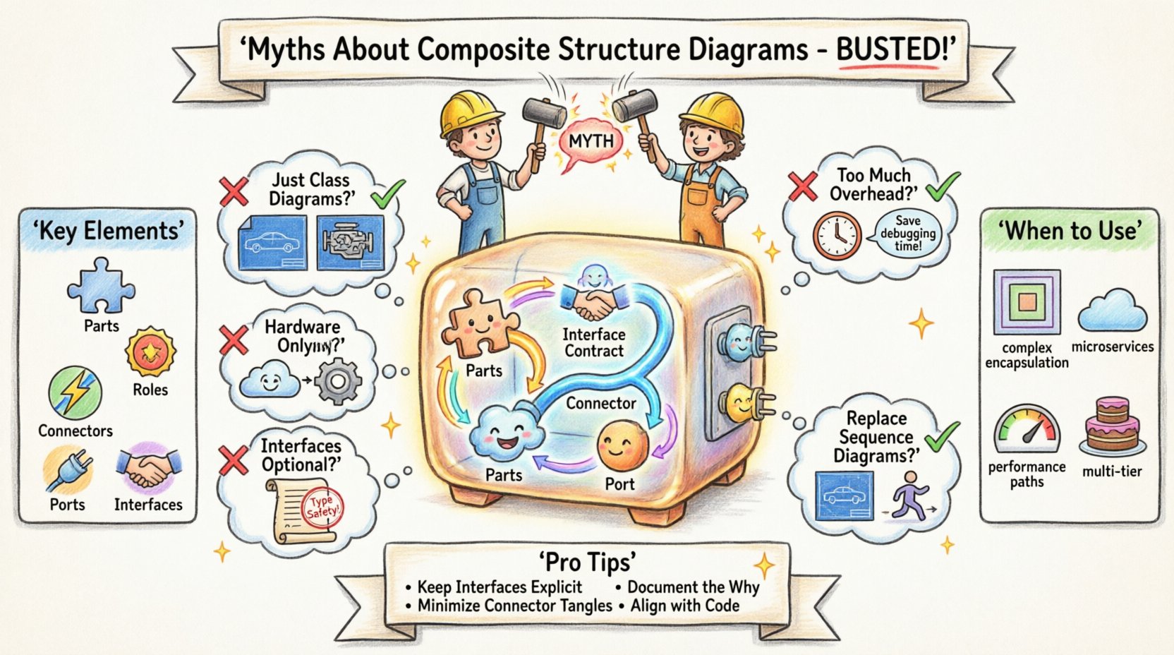
- Parts: The constituent components within the classifier.
- Connectors: The paths that link parts together.
- Interfaces: The services provided or required by the parts.
- Ports: The points of interaction between the classifier and its environment.
Think of a Class Diagram as a blueprint for a car’s exterior and specifications. A Composite Structure Diagram is the cutaway view showing the engine, transmission, and wiring harness inside the chassis. It answers the question: “How does this part actually work internally?”
🚫 Myth 1: They Are Just Class Diagrams on Steroids
The first and most common error is treating a Composite Structure Diagram as a redundant version of a Class Diagram. Teams often ask, “If I have the Class Diagram, why do I need another one?”
The Reality:
- Scope Difference: A Class Diagram models the static structure of the system at the class level. A Composite Structure Diagram models the internal arrangement of parts within a specific classifier.
- Visibility: Class Diagrams show public interfaces and attributes. Composite Structure Diagrams expose the internal wiring and dependencies that are hidden in the standard class view.
- Granularity: In complex systems, a single class might encapsulate a microservice, a hardware module, or a complex algorithm. The Class Diagram cannot show the internal topology of that encapsulation.
Using a Class Diagram for internal structure modeling leads to “spaghetti class” visuals where every dependency is drawn on the same plane. The Composite Structure Diagram introduces a containment hierarchy that visually separates the internal network from the external interface.
🚫 Myth 2: These Diagrams Add Too Much Overhead
Many architects argue that creating detailed internal structure models consumes too much time during the agile development process. They view documentation as a bottleneck rather than a tool for clarity.
The Reality:
- Cost of Change: The time saved in debugging and refactoring often exceeds the time spent modeling. When a system fails, understanding the internal flow of data between parts is faster with a diagram than tracing code.
- Onboarding: New team members struggle to understand legacy systems. A Composite Structure Diagram provides a map of the internal architecture, reducing the ramp-up time for developers.
- Targeted Usage: You do not need to model every class. Reserve this diagram for high-complexity components. If a class is simple, a Class Diagram suffices. If it is a subsystem, the Composite Structure Diagram is required.
Documentation is not about creating artifacts; it is about communicating intent. If the internal complexity is high, the overhead of modeling is an investment in stability.
🚫 Myth 3: They Only Apply to Hardware or Embedded Systems
Historically, these diagrams were popular in hardware engineering to show how physical components fit together. Consequently, software teams often dismiss them as irrelevant to pure software architecture.
The Reality:
- Microservices: In a distributed architecture, a “part” can be a service instance. The diagram maps how services connect internally within a logical boundary.
- Libraries and Frameworks: When building a reusable library, showing the internal components and how they collaborate is vital for API designers.
- Software-Hardware Integration: Even in software, boundaries exist. A driver, a kernel module, or a containerized environment acts as a “part” with specific ports and interfaces.
The concept of “Structure” applies to software just as much as hardware. It defines the topology of the data flow and control flow within a defined boundary.
🚫 Myth 4: Interfaces Are Optional in Internal Modeling
Teams often draw parts and connectors without explicitly defining the Interfaces (provided or required). They assume the code implementation will make the connection clear.
The Reality:
- Contract Clarity: An Interface defines the contract. Without it, the connector is just a wire. The Interface specifies the methods or signals available.
- Decoupling: Parts should depend on Interfaces, not concrete implementations. This allows for swapping internal components without breaking the system.
- Port Definition: Ports are the connection points on the classifier. They must be typed by an Interface to ensure type safety in the design phase.
Skipping interfaces in the diagram leads to tight coupling in the code. If you do not model the Interface, you likely will not enforce the separation of concerns in the implementation.
🚫 Myth 5: They Replace Sequence Diagrams
Some believe that if they show the structure, they do not need to show the behavior. They assume the structural diagram implies how the system operates.
The Reality:
- Static vs. Dynamic: Composite Structure Diagrams are static. They show what exists. Sequence Diagrams are dynamic. They show what happens over time.
- Collaboration: The structure diagram shows that Part A connects to Part B. The Sequence Diagram shows that Part A sends a message to Part B at T1.
- Verification: You use the Sequence Diagram to verify the behavior, and the Composite Structure Diagram to verify the architecture supports that behavior.
Using one in place of the other creates blind spots. You need the map (Structure) and the journey (Sequence) to navigate complex systems.
📊 Comparison: Class vs. Component vs. Composite Structure
To clarify the distinctions, consider the following comparison of UML diagrams often used for structure.
| Diagram Type | Primary Focus | Key Elements | Best Use Case |
|---|---|---|---|
| Class Diagram | Static system structure | Classes, Attributes, Operations | General domain modeling and database schema design |
| Component Diagram | High-level architecture | Components, Interfaces, Dependencies | System integration and deployment planning |
| Composite Structure Diagram | Internal classifier composition | Parts, Roles, Ports, Connectors | Complex internal logic, library design, and subsystems |
Notice the shift in granularity. The Class Diagram is the foundation. The Component Diagram looks at the building blocks. The Composite Structure Diagram looks inside the building block itself.
🛠️ Key Elements Explained
To use these diagrams effectively, one must understand the specific UML notation. Here is a breakdown of the core elements that appear in the diagram.
🔹 Parts
A part is a classifier that is a constituent of another classifier. In the diagram, it appears as a box inside the classifier box. It represents a piece of the internal puzzle.
🔹 Roles
A role describes how a part is used. A single part type might play multiple roles. For example, a database instance might play the role of “Reader” in one context and “Writer” in another. Roles are often shown at the end of a connector.
🔹 Connectors
Connectors define the paths between parts. They represent the data flow or control flow. They do not just link boxes; they link specific roles. This ensures that the interaction is typed correctly.
🔹 Ports
Ports are the interaction points on the boundary of the classifier. They are the “plugs” where external connections happen. A classifier can have multiple ports, each offering different interfaces.
🔹 Interfaces
Interfaces define the behavior without implementation. In a Composite Structure Diagram, they are crucial for defining the contracts between internal parts and between the classifier and the outside world.
🔍 When to Use a Composite Structure Diagram
Not every project requires this level of detail. Applying it indiscriminately creates noise. Use this diagram when:
- Complex Encapsulation: A class or component manages a complex internal state machine that requires multiple sub-components.
- Third-Party Integration: You are wrapping a library or service and need to show how its internal modules interact with your code.
- Performance Critical Paths: You need to visualize data flow bottlenecks within a specific component.
- Multi-Tier Architecture: You need to show how the presentation, logic, and data layers interact within a single logical unit.
If a system is simple enough that a single class handles all logic, do not use this diagram. It is a tool for complexity management.
🧠 Architectural Best Practices
To derive maximum value from these diagrams, follow these architectural principles.
1. Keep Interfaces Explicit
Never rely on implicit knowledge. Every connection between parts should be typed by an Interface. This forces the development team to adhere to contracts.
2. Minimize Connector Complexity
If a connector crosses the boundary of the classifier, it becomes a Port. Do not draw internal connections passing through the boundary. Keep internal topology distinct from external exposure.
3. Document the “Why”
Use notes or annotations to explain why a specific internal structure was chosen. Was it for performance? For security? For testability? The diagram shows the structure; the notes explain the rationale.
4. Align with Code
The diagram must evolve with the code. If the internal parts change, the diagram must update. An outdated diagram is worse than no diagram at all.
🚧 Common Pitfalls to Avoid
Even with good intentions, teams often stumble when creating these models. Here are common errors to watch out for.
- Over-Modeling: Drawing every variable as a part. Parts should represent significant components, not individual variables.
- Ignoring Lifecycle: Failing to show how parts are created or destroyed. While UML has limitations here, noting the lifecycle in comments is helpful.
- Mixing Concerns: Putting behavior details (methods) inside the structure diagram. Keep behavior in Sequence or State diagrams. Structure is about composition.
- Ignoring Ports: Drawing connectors directly to the classifier boundary without defining a Port. This violates the encapsulation principle.
💡 Real-World Scenario: The Payment Gateway
Consider a Payment Gateway component. A Class Diagram shows the class PaymentGateway with methods like processPayment() and validateCard().
A Composite Structure Diagram reveals the internal architecture:
- Part 1:
ValidationService(Required Interface:CardValidator) - Part 2:
TransactionLogger(Provided Interface:LogEntry) - Part 3:
EncryptionModule(Provided Interface:Encryptor) - Connector: Links
EncryptionModuletoTransactionLoggerfor secure logging.
This view highlights that the validation logic is separate from the transaction logic. It also shows that encryption is a distinct concern. If the encryption algorithm changes, only the EncryptionModule needs updating, provided the Interface remains stable. This separation is invisible in the Class Diagram but critical for maintenance.
🔗 Integration with Other Models
A Composite Structure Diagram does not exist in a vacuum. It integrates with the broader modeling ecosystem.
- With Class Diagrams: The classifier in the Composite Structure Diagram is defined in the Class Diagram. The parts are classes or components defined elsewhere.
- With Component Diagrams: A Component Diagram might show the
PaymentGatewayas a single block. The Composite Structure Diagram opens that block to show the internals. - With Deployment Diagrams: It helps determine where parts should be deployed. Some parts might run on a local machine, while others run in the cloud.
This integration ensures consistency. If the Class Diagram changes, the Composite Structure Diagram should be reviewed for validity. If the Deployment Diagram changes, the internal communication paths in the Composite Structure Diagram might need adjustment.
📝 Summary of Architectural Insights
The Composite Structure Diagram is a specialized tool for deep architectural understanding. It bridges the gap between abstract class definitions and concrete implementation details. By clarifying internal boundaries, it reduces the risk of unintended coupling.
Senior architects advocate for its use not as a mandatory artifact for every project, but as a precision instrument for complex systems. When used correctly, it enhances communication, reduces technical debt, and clarifies the responsibilities of internal components.
Ignore the myths. Embrace the structure. Model the internals with clarity, and build systems that are robust and maintainable.
📚 Frequently Asked Questions
Is this diagram supported by all UML tools?
Most modern UML modeling tools support Composite Structure Diagrams. However, some lightweight diagramming tools may lack full support for ports and roles.
Can I use this for database schemas?
Yes, if you are modeling the internal structure of a database engine or a complex ORM layer. It is less common for simple relational schemas.
How detailed should the diagram be?
Focus on the critical paths and high-value components. Do not model every method. Model the parts that define the architecture.
Does this diagram help with testing?
Indirectly. By defining interfaces and ports clearly, it aids in defining test stubs and mocks for unit testing internal parts.