


Understanding the internal architecture of complex systems is crucial for robust software design. While class diagrams provide a high-level view of objects and their relationships, they often fail to capture the detailed internal composition of a single classifier. This is where the Composite Structure Diagram becomes indispensable. This guide will walk you through the essential steps to create these diagrams effectively, ensuring your system models are precise, maintainable, and clear.
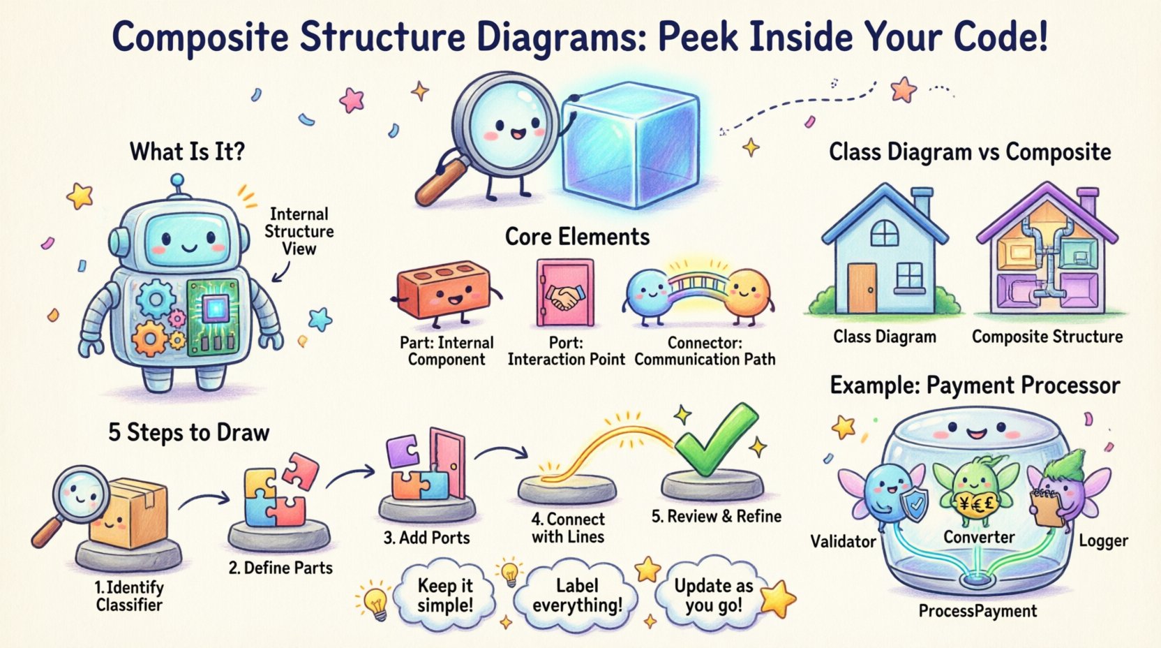
🔍 What Is a Composite Structure Diagram?
A Composite Structure Diagram is a specialized type of UML diagram that shows the internal structure of a classifier. It reveals how the parts inside a class or component are connected and interact with each other. Think of it as an X-ray view of a system element, showing the inner workings rather than just the outer interface.
- Focus: Internal structure and delegation.
- Scope: Specific to a single classifier (like a class or component).
- Utility: Shows how parts are wired together to fulfill the whole.
Unlike a standard Class Diagram, which lists attributes and methods, this diagram focuses on the relationships between internal parts. It is particularly useful for modeling complex systems where a single logical unit is composed of multiple interacting sub-units.
🧩 Core Elements and Concepts
To draw an accurate diagram, you must understand the specific building blocks. Each element serves a distinct purpose in defining the internal topology.
1. Part 🧱
A Part represents an instance of a classifier that is owned by the composite. It is a structural feature. When you define a part, you are declaring that the composite contains an object of a specific type.
- Notation: A rectangle with the part name and type.
- Role: Defines the internal components.
2. Port 🚪
A Port is a distinct point of interaction for the composite or its parts. It defines how the internal parts connect to the outside world or to other internal parts. Ports encapsulate the interface, hiding internal implementation details.
- Notation: A small circle attached to the part or composite.
- Role: Defines interaction points (provided or required interfaces).
3. Connector 🔗
Connectors link ports together. They define the flow of information or control between parts. A connector can link two internal ports, an internal port to an external port, or an external port to a part.
- Notation: A solid line connecting the ports.
- Role: Establishes communication paths.
4. Interaction Use 🔄
An Interaction Use represents a use of a specific interaction (like a sequence diagram) within the structure. It allows you to model behavior without drawing it inline.
- Notation: A rectangle with the interaction name.
5. Execution Environment 🌐
This defines the environment where the parts execute. It helps model deployment and runtime contexts within the structure.
📊 Comparison: Class Diagram vs. Composite Structure Diagram
Understanding when to use which diagram is vital for clear modeling. Use the table below to differentiate their purposes.
| Feature | Class Diagram | Composite Structure Diagram |
|---|---|---|
| Focus | Static structure of classes | Internal structure of a single classifier |
| Detail Level | High-level attributes and methods | Low-level parts and internal connections |
| Relationships | Aggregation, Association, Inheritance | Delegation, Composition, Internal Wiring |
| Use Case | Database schema, general architecture | Component internals, hardware subsystems |
🛠️ Step-by-Step: How to Draw the Diagram
Creating a Composite Structure Diagram requires a methodical approach. Follow these steps to ensure accuracy and clarity.
Step 1: Identify the Classifier
Start by selecting the specific class or component you want to analyze. This becomes the main container of your diagram. Ask yourself: “What is the internal complexity of this specific unit that needs showing?” If the unit is simple, a class diagram might suffice. If it has internal logic or multiple sub-components, proceed.
Step 2: Define the Parts
Break down the classifier into its constituent parts. These are the objects that make up the whole. List them out clearly.
- Identify Dependencies: What does this part need to function?
- Define Types: Assign a specific class or interface to each part.
- Assign Names: Give each part a unique identifier within the context of the composite.
Step 3: Determine Interfaces (Ports)
For each part, decide how it interacts. Does it require a service from another part? Does it provide a service to the outside world? Create ports for these interactions.
- Provided Interfaces: Draw a “lollipop” symbol on the port.
- Required Interfaces: Draw a “socket” symbol on the port.
- Connectivity: Ensure every required interface has a matching provided interface.
Step 4: Establish Connections (Connectors)
Draw lines between the ports to show how data or control flows. This is the “wiring” of the system.
- Internal Connections: Connect parts to other parts within the same composite.
- Delegation: Connect an internal part’s port to the composite’s external port. This shows that the composite delegates requests to the part.
Step 5: Refine and Review
Once the structure is drawn, review it for consistency. Check if all required interfaces are met. Ensure no circular dependencies exist that might cause runtime issues. Verify that the notation matches the standard UML conventions.
💡 Practical Example: Payment Processing System
Let us apply this knowledge to a real-world scenario. Consider a PaymentProcessor class. This class is not just a simple calculator; it handles validation, currency conversion, and transaction logging.
Scenario Breakdown
- Composite: PaymentProcessor
- Part 1: Validator (Checks card details)
- Part 2: Converter (Handles currency)
- Part 3: Logger (Records transactions)
Connections
- The Validator requires a CardChecker interface.
- The Converter requires a ExchangeRate interface.
- The Logger provides a LogAccess interface.
- The PaymentProcessor exposes a ProcessPayment port.
In the diagram, the PaymentProcessor port delegates to the Validator and Converter. The Validator connects to the Converter if validation depends on currency conversion. The Logger connects to the main flow to ensure every transaction is recorded.
⚠️ Common Pitfalls to Avoid
Even experienced modelers can make mistakes when defining internal structures. Being aware of these common errors can save you time during the review process.
- Overcomplicating the Diagram: Do not show every single variable. Focus on structural interactions, not data storage details.
- Ignoring Interfaces: A diagram without ports and interfaces is just a collection of boxes. Define how parts talk to each other.
- Mixing Levels: Do not mix high-level component diagrams with low-level part details in the same view. Keep the scope consistent.
- Neglecting Lifecycle: Ensure parts are created and destroyed correctly within the lifecycle of the composite. A part should not outlive the composite without proper management.
🔗 Integration with Other Diagrams
A Composite Structure Diagram does not exist in isolation. It complements other UML diagrams in your toolkit.
With Sequence Diagrams
Use a Sequence Diagram to show the dynamic behavior that occurs within the connections defined in your Composite Structure Diagram. The sequence diagram shows the when, while the structure diagram shows the where.
With Component Diagrams
Component Diagrams show the system architecture at a higher level. The Composite Structure Diagram dives deeper into a specific component. Use the Component Diagram for the big picture and the Composite Structure Diagram for the deep dive.
With Deployment Diagrams
Deployment Diagrams show physical nodes. Composite Structure Diagrams show logical parts. You can map the parts from your structure diagram to the nodes in your deployment diagram to understand physical distribution.
📝 Best Practices for Documentation
To ensure your diagrams are useful for the team, follow these documentation standards.
- Use Clear Labels: Name every port and part clearly. Avoid generic names like “Part1” or “ObjectA”.
- Group Related Parts: Visually group parts that are functionally related to improve readability.
- Document Delegation: Clearly mark which internal parts handle external requests via delegation connectors.
- Version Control: Treat these diagrams as code. Update them whenever the internal structure of the class changes.
- Limit Complexity: If a class has too many internal parts, consider splitting it into multiple smaller classes or using a Substructure Diagram.
🧠 Advanced Concepts: Internal Activity
Sometimes, the interaction between parts involves complex logic. You can embed activity diagrams within a part to show this behavior. This is known as an Internal Activity Diagram.
- Triggering: Define what event starts the internal activity.
- Flow: Show the sequence of actions performed by the part.
- Output: Define the result sent back to the connector.
This level of detail is reserved for highly complex systems where the logic inside a single class is non-trivial.
📈 Maintenance and Evolution
Software evolves. As requirements change, the internal structure of your classes will likely change. A Composite Structure Diagram is a living document.
- Refactoring: If you refactor a class, update the diagram immediately. Do not let the model drift from reality.
- Decomposition: If a part becomes too complex, it can become a composite in its own right. Create a new diagram for that part.
- Review Cycles: Include these diagrams in your regular architecture review meetings. Ensure the team agrees on the internal wiring.
🚀 Summary
Creating a Composite Structure Diagram is a powerful way to visualize the internal mechanics of your software components. It bridges the gap between high-level architecture and low-level implementation details. By defining parts, ports, and connectors, you provide a clear map for developers to understand how data flows within a system.
Remember to:
- Identify the main classifier clearly.
- Define all internal parts and their types.
- Specify interaction points using ports.
- Wire them together with connectors.
- Review for consistency and clarity.
With practice, drawing these diagrams will become a natural part of your design process, leading to more robust and maintainable software systems.