


In the complex world of software architecture, visual communication serves as the bridge between abstract logic and concrete implementation. Among the various tools available within the Unified Modeling Language (UML), the Composite Structure Diagram stands out for its specific utility. It offers a window into the internal architecture of a classifier, revealing how parts interact to form a cohesive unit. For development teams, understanding and utilizing this diagram type correctly can significantly reduce ambiguity and improve system maintainability.
This guide explores the essential practices for creating effective Composite Structure Diagrams. We will examine the structural elements, discuss collaboration strategies, and outline specific behaviors to adopt or avoid. By adhering to these principles, teams can ensure their architectural documentation remains clear, accurate, and useful throughout the software lifecycle.
🏗️ Understanding the Internal Blueprint
A Composite Structure Diagram is not merely a static image; it is a representation of internal organization. Unlike a Class Diagram, which focuses on relationships between classes, or a Sequence Diagram, which focuses on interactions over time, this diagram type focuses on the composition of parts within a single unit. It answers the question: “What makes up this specific component?”
When teams fail to visualize internal structure, they often encounter issues during refactoring. A developer might modify a class without realizing it is composed of several interdependent parts, leading to unexpected breakage elsewhere in the system. Therefore, clarity in these diagrams is not optional; it is a requirement for robust engineering.
🧩 Core Components Explained
To draw these diagrams effectively, one must understand the fundamental building blocks. Each element serves a distinct purpose in defining the contract and the implementation of the structure.
- Parts: These represent the instances of classifiers that make up the composite structure. Think of them as the physical components within a larger machine.
- Roles: A part may play multiple roles within the structure. A single component might act as a data source in one context and a consumer in another.
- Ports: These are the interaction points where parts connect to the outside world or to other parts. They define the interface for communication.
- Connectors: These link ports to roles or other ports, establishing the flow of data or control between components.
- Interfaces: The diagram often specifies the interface that a port requires or provides. This ensures that the internal parts can communicate with external systems correctly.
When defining these elements, precision is key. Vague naming conventions lead to confusion. If a port is labeled simply “Input,” the team does not know what kind of data enters or what protocol it uses. Specificity reduces cognitive load during code reviews.
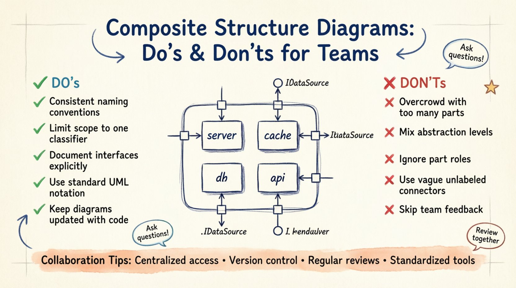
✅ Essential Practices for Clarity
Creating a diagram that aids understanding requires discipline. The following practices have proven effective in professional environments.
1. Maintain Consistent Naming Conventions
Every label on the diagram should follow a standardized format. If parts are named using the class name, do not switch to abbreviations halfway through. Consistency allows team members to scan the diagram quickly and locate the information they need without decoding different naming styles.
2. Limit the Scope of Each Diagram
It is tempting to show the entire system in one massive diagram. This approach usually fails because the diagram becomes unreadable. Instead, break down the composite structure into manageable chunks. Focus on one major classifier at a time. This modular approach allows developers to understand the context of a specific component without getting lost in the wider architecture.
3. Document Interfaces Explicitly
Do not assume that the interface is self-evident. Clearly mark which ports provide services and which require them. Use standard notation to indicate the direction of dependency. This prevents integration errors where a part expects a service that is not available.
4. Use Standard Notation
Adhere to the standard UML specifications for this diagram type. Deviating from standard shapes or line styles creates confusion for anyone familiar with the industry standards. Stick to the established rules for ports, connectors, and roles to ensure universal understanding.
5. Keep It Up to Date
A diagram that does not reflect the current code is worse than no diagram at all. It creates a false sense of security. Establish a workflow where the diagram is updated alongside the code. If a part is removed or a port is added, the visual representation must change immediately.
❌ Common Pitfalls to Avoid
Even experienced architects can fall into traps that reduce the value of their documentation. Recognizing these pitfalls is the first step toward avoiding them.
1. Overcrowding with Too Many Parts
Displaying every single variable or minor class within a composite structure creates visual noise. Focus on the significant parts that define the behavior. If a part is trivial and does not affect the interaction, it does not need to be included in this specific diagram.
2. Mixing Levels of Abstraction
Do not combine high-level architectural views with low-level implementation details in the same view. A Composite Structure Diagram should focus on the composition of the classifier. If you need to show the internal logic of a part, use a separate activity or class diagram. Mixing these layers obscures the structural relationships.
3. Ignoring the Role of the Part
Parts often serve multiple functions. Failing to label the role a part plays can lead to ambiguity. For example, a database connector might act as a reader in one scenario and a writer in another. Clearly label these roles to prevent misunderstandings about data flow.
4. Using Vague Connectors
A connector without a label implies a generic connection. In complex systems, the type of connection matters. Is it a synchronous call? Is it an event subscription? Labeling connectors with their specific behavior helps developers understand the runtime implications of the structure.
5. Neglecting Team Feedback
Creating a diagram in isolation often leads to blind spots. If the team does not review the diagram before it is finalized, critical errors may slip through. Collaboration ensures that the diagram reflects the actual mental model of the entire engineering group.
📊 Do’s vs Don’ts Comparison
The following table summarizes the critical distinctions between effective and ineffective practices.
| Category | Do ✅ | Don’t ❌ |
|---|---|---|
| Scope | Focus on one classifier at a time | Show the entire system in one view |
| Naming | Use consistent, descriptive names | Use abbreviations or vague terms |
| Interfaces | Explicitly define required and provided interfaces | Assume interfaces are self-explanatory |
| Maintenance | Update diagram with code changes | Let the diagram drift from reality |
| Detail Level | Highlight significant parts and roles | Include every minor variable or method |
| Collaboration | Review with the team before finalizing | Create in isolation without feedback |
🤝 Collaboration Strategies for Distributed Teams
In modern engineering, teams are often distributed across different time zones and locations. This presents unique challenges for maintaining architectural clarity.
Centralized Access: Ensure the diagram repository is accessible to all relevant stakeholders. If a developer in one region cannot access the diagram, they cannot contribute to the design discussion.
Version Control: Treat diagrams as code. Store them in a version control system. This allows teams to track changes, revert mistakes, and see who modified a specific part of the structure. It creates an audit trail for architectural decisions.
Regular Review Sessions: Schedule periodic reviews where the team walks through the diagrams together. This ensures everyone has the same understanding of the internal structure. It also serves as a knowledge transfer mechanism for new team members.
Standardized Tools: While you should avoid specific vendor lock-in, ensure the team uses compatible tools for viewing and editing. Disparate tools can lead to formatting issues or incompatibility that hinders collaboration.
🔄 Maintaining Diagram Integrity Over Time
Software evolves. Requirements change, and features are added or removed. A Composite Structure Diagram that was accurate last quarter may be obsolete today. Maintaining integrity requires a proactive approach.
One effective strategy is to link the diagram directly to the codebase. If a part in the diagram corresponds to a specific class file, ensure that file is referenced. When the file is modified, the diagram should be flagged for review. This prevents the “documentation debt” that accumulates when diagrams are updated less frequently than the code.
Additionally, establish a policy for diagram lifecycle. Define when a diagram is considered “complete” and when it is considered “deprecated.” This helps teams decide when to invest effort in updating a diagram versus when to focus on the code itself.
🚀 Integrating with Agile Workflows
Agile methodologies emphasize iterative development and frequent delivery. How do static architectural diagrams fit into this pace?
They should be treated as living artifacts. In a sprint planning session, if a new feature involves a significant change to the internal structure, the diagram should be updated as part of the definition of done. This ensures that the visual documentation keeps pace with the delivery of value.
Do not view the diagram as a preliminary step that is discarded after implementation. It is a reference point for future work. When a team member needs to understand how a legacy component works, the Composite Structure Diagram provides the necessary context without requiring them to read the entire codebase.
🔍 Common Scenarios and Applications
Understanding where to apply this diagram type is crucial. It is not a universal solution for every design problem.
Microservices: When designing a microservice, this diagram helps visualize the internal modules that make up the service. It clarifies which internal components communicate with external services and which remain private.
Refactoring: Before refactoring a complex class, draw the current structure. Compare it with the proposed structure. This visual comparison highlights the impact of the change and identifies potential risks.
Legacy Systems: For legacy code, this diagram serves as a discovery tool. By reverse-engineering the structure, teams can create a map of the existing internal organization, which is vital for planning modernization efforts.
🔗 Final Considerations
The effectiveness of a Composite Structure Diagram lies in its ability to communicate complex internal relationships simply. It is a tool for alignment. When everyone on the team looks at the diagram and sees the same structure, collaboration becomes smoother and errors become less frequent.
Remember that the goal is not to create a perfect drawing, but to create a useful one. If a diagram confuses the team, it needs to be simplified. If it helps them understand the system, it has served its purpose. Focus on clarity, accuracy, and maintenance. These principles will ensure that your architectural documentation remains a valuable asset to your team.
By following the guidelines outlined in this article, teams can leverage the power of Composite Structure Diagrams to build more robust, maintainable, and understandable software systems. The effort invested in proper diagramming pays dividends in reduced technical debt and improved team velocity.