


In the intricate landscape of system architecture, visualizing how components interact internally is critical for robust design. While standard class diagrams describe static relationships, they often fail to capture the internal mechanics of a specific class or component. This is where the Composite Structure Diagram becomes indispensable. It reveals the internal organization, providing a clear view of the structure and behavior of a composite element. This guide explores the underlying logic, components, and strategic application of this powerful UML notation.
🏗️ What is a Composite Structure Diagram?
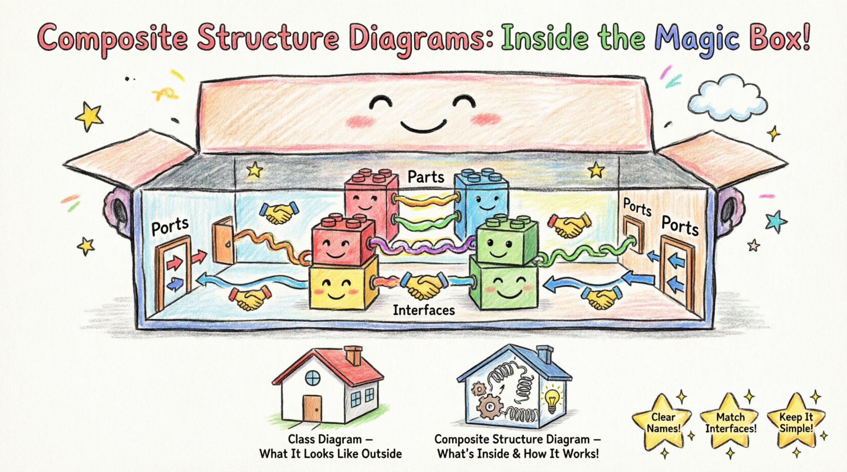
A Composite Structure Diagram is a specialized type of UML diagram that illustrates the internal structure of a classifier. It goes beyond external interfaces to show the parts that make up a whole, how they connect, and how they collaborate to fulfill a specific function. Think of it as an X-ray of a software class or a mechanical system, exposing the gears and levers inside the casing.
This diagram is particularly useful when:
- A class is complex and needs internal decomposition.
- You need to show how parts collaborate to realize a specific interface.
- There is a need to define internal roles and ports for interaction.
- The system relies on nested structures or composite behaviors.
Unlike a standard class diagram, which focuses on attributes and methods, the Composite Structure Diagram focuses on collaboration and deployment of internal parts. It bridges the gap between logical design and physical implementation.
🧩 The Core Components: Anatomy of the Logic
To understand the hidden logic, one must understand the building blocks. Every composite structure diagram is constructed from specific elements that define how the system operates internally.
1. Parts: The Building Blocks
Parts represent the internal instances of classifiers. They are the actual objects or components that reside within the composite structure. A part is not just a variable; it is a defined unit of functionality.
- Multiplicity: A part can have a range of instances (e.g., 1..*). This defines how many internal components exist.
- Visibility: Parts can be public, private, or protected, controlling access from outside the composite.
- Role: A part plays a specific role within the composite structure, which may differ from its general classifier definition.
2. Ports: The Entry and Exit Points
Ports are the interaction points between the composite structure and its environment, or between internal parts. They encapsulate the interface of a part.
- Provided Interfaces: Indicate services that the part offers to the outside world.
- Required Interfaces: Indicate services that the part needs from the outside world to function.
- Directionality: Ports define the flow of data and control signals.
3. Connectors: The Pathways
Connectors link parts to each other or to the boundary of the composite structure. They represent the communication channels.
- Internal Connectors: Link parts within the same composite structure.
- External Connectors: Link parts to the interface of the composite structure.
- Binding: Connectors bind the required interface of one part to the provided interface of another.
4. Interfaces: The Contracts
Interfaces define the visible behavior of a part without revealing its implementation details. In a composite structure diagram, they define the contract between the composite and its parts.
- Usage: Shows which interface a part needs.
- Realization: Shows which interface a part implements.
🔄 The Logic of Internal Interaction
The true power of this diagram lies in how it models the flow of control and data. It is not merely a static snapshot; it implies dynamic behavior through its connections.
Collaboration Logic
When designing a system, you often need to ensure that internal parts work together seamlessly. The diagram models this collaboration explicitly.
- Decoupling: By defining ports and interfaces, you decouple internal parts from external dependencies.
- Encapsulation: Internal logic remains hidden unless exposed through a defined port.
- Flexibility: You can swap internal parts as long as they adhere to the same interface contract.
Role-Based Design
One part can play multiple roles within a system. The diagram allows you to specify these roles clearly. For instance, a database connection might play the role of a Reader in one context and a Writer in another. This role-based approach simplifies complex interactions.
📊 Comparing Diagram Types
Understanding where this diagram fits in the broader UML suite is essential for effective modeling. The table below outlines the distinctions.
| Diagram Type | Primary Focus | Best Used For |
|---|---|---|
| Class Diagram | Static structure, attributes, methods | High-level system overview |
| Component Diagram | Physical components, deployment | System architecture and deployment |
| Composite Structure Diagram | Internal structure, parts, ports | Complex class internals, nested structures |
| Sequence Diagram | Dynamic interaction over time | Behavioral flow and timing |
🛠️ Strategic Implementation in System Design
Applying this logic requires discipline. It is not a tool for every scenario, but a specific solution for specific architectural challenges.
When to Use
- Complex Aggregations: When a class is composed of multiple sub-components that need separate management.
- Interface Realization: When you need to show how a composite structure implements a larger system interface.
- Refinement: When refining a high-level component into its internal parts.
- Boundary Definition: When defining the exact boundary between internal logic and external exposure.
When to Avoid
- Simple Classes: If a class has no internal structure, a standard class diagram suffices.
- Behavioral Focus: If the focus is on message passing over time, use a sequence diagram.
- Deployment Focus: If the focus is on physical hardware or network topology, use a deployment diagram.
🚧 Common Pitfalls and Best Practices
Designers often make mistakes that obscure the logic rather than clarify it. Adhering to best practices ensures clarity and maintainability.
Pitfall 1: Over-Engineering
Do not create a composite structure diagram for every class. This leads to model bloat and confusion. Use it only where internal complexity justifies the overhead.
Pitfall 2: Ignoring Multiplicity
Failing to specify the multiplicity of parts can lead to ambiguity. Always define how many instances of a part exist (e.g., 1, 0..1, *).
Pitfall 3: Mixing Levels of Abstraction
Do not mix high-level components with low-level implementation details in the same view. Keep the granularity consistent within the diagram.
Best Practice 1: Clear Naming
Use descriptive names for parts and ports. Avoid generic terms like Part1 or Object2. Names should reflect the function, such as Authenticator or Logger.
Best Practice 2: Consistent Interfaces
Ensure that the interfaces used by parts match the contracts defined at the composite level. This maintains the integrity of the system design.
Best Practice 3: Documentation
Use notes to explain complex logic that cannot be visually represented. Textual annotations complement the visual elements effectively.
🔬 Advanced Scenarios: Nested Classifiers
One of the most powerful features of the composite structure is the ability to define nested classifiers. This allows for a hierarchical view of structure.
Inner Structure
Within a composite structure, you can define another classifier. This is useful for modeling sub-systems that are logically bound to the parent but have their own internal logic.
- Scope: The nested classifier is visible only within the context of the parent.
- Reusability: While nested, they can still be referenced if the scope allows.
- Complexity Management: Breaking down a large structure into smaller, nested views helps manage cognitive load.
Refinement
Refinement allows you to show how a logical part is implemented physically. You can link a logical interface to a physical realization using this diagram. This is crucial for bridging the gap between design and code.
🔗 Integration with Other Diagrams
This diagram does not exist in isolation. It integrates with other UML diagrams to provide a complete picture of the system.
With Class Diagrams
While the class diagram shows the type definition, the composite structure diagram shows the instance composition. They work together to define both the blueprint and the assembly.
With State Machine Diagrams
State machines describe the behavior of a classifier. The composite structure defines the parts that participate in that behavior. Combining them shows how parts transition states together.
With Deployment Diagrams
Deployment diagrams show where software runs. Composite structure diagrams show what software contains. Together, they map the logical structure to the physical environment.
🧭 Navigating the Logic for Success
Mastering the logic behind composite structure diagrams requires a shift in perspective. It moves from thinking about objects as isolated entities to viewing them as systems of interacting parts. This shift is fundamental for scalable architecture.
Key Takeaways
- Internal Focus: It reveals what is hidden inside a class or component.
- Collaboration: It emphasizes how parts work together, not just how they relate.
- Interfaces: It relies heavily on interface definitions for communication.
- Flexibility: It supports swapping internal implementations without changing external contracts.
Future Considerations
As systems become more distributed and microservice-oriented, the logic of composite structures remains relevant. It helps define the boundaries of a service and how internal agents within that service interact. Understanding this logic prepares architects for complex, modular systems.
📝 Summary of Structural Elements
To ensure quick reference, here is a summary of the core elements and their functions.
- Classifier: The container of the structure (e.g., a Class or Component).
- Part: An instance of a classifier within the container.
- Port: A distinct point of interaction for a part.
- Connector: A link between ports or between a part and an interface.
- Interface: A contract defining operations available at a port.
- Node: (Optional) Can represent the physical node where the structure resides.
By adhering to these principles, you create models that are not only visually clear but logically sound. The composite structure diagram serves as a bridge between abstract design and concrete implementation, ensuring that the hidden logic of your system is transparent and manageable.