


Introduction to Use Case Driven Development
Use Case Driven Development (UCDD) is a software development methodology that places use cases at the center of the entire development lifecycle. Originating from the Unified Modeling Language (UML) and popularized by methodologies like the Rational Unified Process (RUP), UCDD emphasizes capturing system requirements from the user’s perspective to drive analysis, design, implementation, and testing. Unlike traditional approaches that might focus heavily on data or functions in isolation, UCDD uses use cases—descriptions of how users interact with the system to achieve goals—to ensure the software meets real-world needs.
The core idea is that use cases represent the “what” of the system (expected behavior) without delving into the “how” (implementation details) too early. This user-centric approach helps bridge the gap between stakeholders, analysts, and developers, reducing misunderstandings and promoting iterative development. Benefits include improved requirements traceability, better risk management through prioritization of critical use cases, and enhanced reusability via relationships like includes and extends.
UCDD is particularly effective for complex systems where user interactions are key, such as e-commerce platforms, banking apps, or enterprise software. It integrates well with agile practices, where use cases can evolve alongside user stories.
The Process of Use Case Driven Development
The UCDD process is iterative and incremental, typically spanning the software development lifecycle. Below is a step-by-step breakdown, drawing from standard UML practices and real-world applications. I’ll use an example of building an online shopping system to illustrate each step.
Step 1: Elicit Requirements and Identify Stakeholders
- Objective: Gather high-level requirements by identifying who interacts with the system (actors) and what they need to accomplish (use cases).
- Activities:
- Conduct interviews, workshops, or surveys with stakeholders (e.g., end-users, business owners, domain experts).
- Ask guiding questions for actors: Who uses the system? Who maintains it? What external systems interact with it?
- For use cases: What goals does each actor want to achieve? What information do they provide or receive?
- Example: In an online shopping system, actors might include “Customer,” “Administrator,” and “Payment Gateway” (an external system). Use cases could be “Browse Products,” “Place Order,” and “Manage Inventory.”
- Outputs: A list of actors and preliminary use cases, often captured in textual form.
- Tips: Start broad and refine iteratively. Prioritize based on business value, risk, or frequency of use.
Step 2: Describe Use Cases in Detail
- Objective: Flesh out each use case with scenarios, flows, and conditions to make them actionable.
- Activities:
- Write use case descriptions using a structured template: Include name, actors, preconditions, postconditions, main flow (happy path), alternative flows (variations), and exceptions (error handling).
- Use natural language for clarity, focusing on user-system interactions.
- Identify relationships: <<include>> for mandatory reused behavior (e.g., “Login” included in “Place Order”), <<extend>> for optional extensions (e.g., “Apply Coupon” extending “Checkout”), and generalization for inheritance (e.g., “Pay by Credit” generalizing “Payment”).
- Example: For “Place Order”:
- Preconditions: Customer is logged in, cart has items.
- Main Flow: Select shipping, enter payment, confirm order.
- Alternative: Guest checkout.
- Exception: Payment failure.
- Outputs: Detailed textual use case specifications.
- Tips: Keep descriptions concise (aim for 1-2 pages per use case) and scenario-based to facilitate testing later.
Step 3: Create Use Case Diagrams
- Objective: Visualize the system’s context, actors, use cases, and relationships.
- Activities:
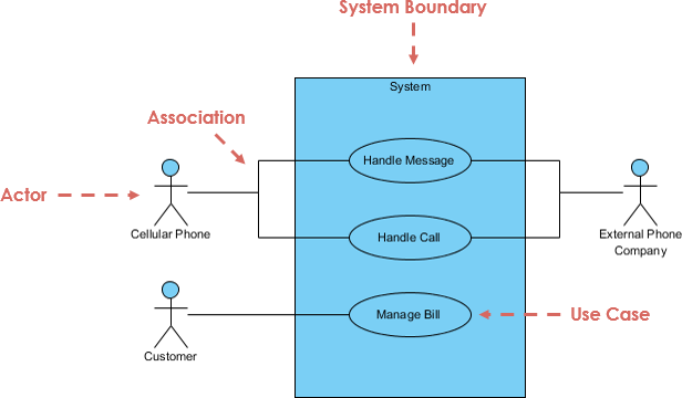
- Draw a UML use case diagram: Represent the system as a boundary box, actors as stick figures or icons outside the box, use cases as ovals inside, and connections as lines.
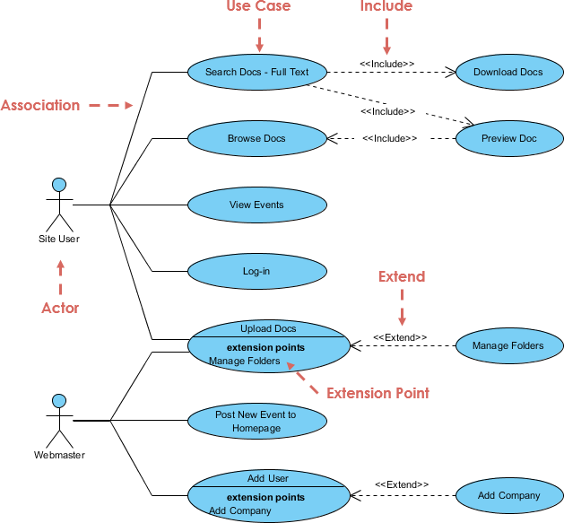
- Add stereotypes for relationships (e.g., dashed arrows for <<include>> and <<extend>>).
- Validate for completeness: Ensure every actor connects to at least one use case, and avoid overcrowding (limit to 5-10 use cases per diagram; use packages for larger systems).
- Example: In the online shopping system, the diagram shows “Customer” connected to “Browse Products,” “Add to Cart,” and “Place Order,” with “Place Order” including “Login” and extending to “Apply Coupon.”
- Outputs: UML use case diagrams.
- Tips: Use tools for drawing to ensure standards compliance. Diagrams should be simple and focus on external behavior.
To illustrate, here’s an example UML use case diagram for an online shopping system:
Step 4: Analyze and Refine Use Cases
- Objective: Ensure use cases are robust, consistent, and aligned with requirements.
- Activities:
- Review for gaps, ambiguities, or overlaps.
- Derive additional artifacts: From use cases, create activity diagrams for flows, sequence diagrams for interactions, or class diagrams for data models.
- Prioritize use cases for iterations (e.g., implement core ones first).
- Example: Analyze “Place Order” to identify needed classes like “Order,” “Product,” and “Payment.”
- Outputs: Refined use cases and supporting models.
- Tips: Use traceability matrices to link use cases to requirements.
Step 5: Drive Design and Implementation
- Objective: Use use cases to guide architectural and coding decisions.
- Activities:
- Map use cases to design elements: Sequence diagrams for object interactions, state diagrams for lifecycles.
- Implement code based on use case flows, ensuring modularity (e.g., reusable components for included use cases).
- Iterate: Prototype critical use cases and gather feedback.
- Example: Code the “Place Order” flow, integrating payment APIs.
- Outputs: Design models and initial code.
- Tips: Focus on behavior over structure initially.
Step 6: Testing and Validation
- Objective: Verify the system against use cases.
- Activities:
- Generate test cases from use case scenarios (main, alternative, exceptions).
- Perform unit, integration, and system testing.
- Validate with users via acceptance testing.
- Example: Test “Place Order” with valid/invalid payments.
- Outputs: Test plans, reports, and validated software.
- Tips: Use cases make testing scenario-driven and comprehensive.
| Step | Key Activities | Outputs | Tools/Techniques |
|---|---|---|---|
| 1: Elicit Requirements | Identify actors & use cases via stakeholder input | Actor/use case lists | Interviews, questionnaires |
| 2: Describe Use Cases | Detail flows, preconditions, exceptions | Textual specifications | Templates, relationships (include/extend) |
| 3: Create Diagrams | Visualize system context | UML diagrams | Drawing tools |
| 4: Analyze & Refine | Review, derive models | Refined artifacts | Traceability matrices |
| 5: Design & Implement | Map to designs, code | Models, code | Sequence/activity diagrams |
| 6: Test & Validate | Generate tests from scenarios | Test results | Scenario-based testing |
This process is iterative; revisit steps as new insights emerge.
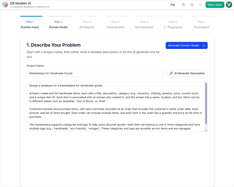
How Visual Paradigm’s Drawing and AI-Powered Features Simplify the Process
Visual Paradigm is a powerful UML modeling tool that streamlines UCDD through intuitive drawing capabilities and advanced AI features. It supports the entire lifecycle, from requirements to deployment, making complex tasks faster and more accurate. Here’s how it significantly simplifies each aspect:
Drawing Features for Simplified Modeling
Visual Paradigm’s drag-and-drop interface allows effortless creation of UML diagrams, including use case diagrams. Users can:
- Quickly add actors, use cases, and relationships with pre-built shapes and connectors that auto-align and enforce UML standards.
- Organize large models using layers, packages, or sub-diagrams to avoid clutter.
- Export diagrams to formats like PDF or integrate with tools like Jira for collaboration. This reduces manual effort; for instance, drawing a use case diagram takes minutes instead of hours in generic tools, ensuring consistency and professionalism.
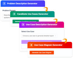
AI-Powered Features for Automation and Enhancement
Visual Paradigm integrates AI to automate repetitive tasks, analyze content, and generate artifacts, cutting development time by up to 50% in use case-heavy projects. Key AI features relevant to UCDD include:
- AI Use Case Description Generator: Automatically creates detailed textual descriptions from brief inputs or existing diagrams. For Step 2, input a use case name like “Place Order,” and AI generates flows, preconditions, and exceptions, saving hours of writing and ensuring completeness.
- AI Use Case Diagram Refinement Tool: Refines diagrams by suggesting <<include>> and <<extend>> relationships, optimizing for reuse. In Step 3, upload a rough diagram, and AI analyzes it to add missing elements or improve structure, reducing errors in complex systems.
- AI Use Case Scenario Analyzer: Transforms use case descriptions into decision tables or activity diagrams. For Step 4, it identifies scenarios and exceptions, automating refinement and derivation of supporting models like sequence diagrams.
- AI Base Use Case Diagram Analyzer: Generates reports, flow of events, and test cases from diagrams. In Steps 5-6, it auto-creates test scripts from use cases, enhancing traceability and speeding up testing.
- AI Chatbot for Visual Modeling: Chat with AI to generate diagrams on-the-fly (e.g., “Create a use case diagram for online shopping”). This supports rapid prototyping in early steps, importing results directly into projects.

- Other AI Tools: Features like AI Textual Analysis extract requirements from documents, while AI Development Plan Generator outlines iterations based on prioritized use cases, aiding project management.
Overall, these features simplify UCDD by automating generation (e.g., descriptions from scratch), refinement (e.g., relationship analysis), and integration (e.g., linking to other UML diagrams). For teams, this means faster iterations, fewer revisions, and better collaboration—turning a manual, error-prone process into an efficient, AI-assisted workflow. Visual Paradigm’s AI is accessible in versions like 17.3 and above, with desktop and online options.
By leveraging Visual Paradigm, developers can focus on innovation rather than tedium, making UCDD accessible even for beginners or large-scale projects.