


The architecture of software systems has shifted dramatically over the last decade. As complexity grows, the need for precise structural documentation becomes critical. Composite Structure Diagrams (CSD) have long been a staple in Unified Modeling Language (UML) for depicting the internal structure of a classifier. However, the landscape of development is changing. Cloud-native technologies, microservices architectures, and the integration of artificial intelligence are pushing these diagrams beyond their traditional static definitions. This guide examines the trajectory of Composite Structure Diagrams and how they adapt to contemporary engineering challenges.
Understanding the Current State of Composite Structure Diagrams 📋
Before projecting into the future, it is necessary to establish what a Composite Structure Diagram represents today. In standard UML, a CSD shows the internal arrangement of parts, roles, and interfaces within a classifier. It answers the question: What makes up this component?
Traditionally, this has been used for:
- Defining the internal hierarchy of a class or component.
- Specifying the ports and interfaces through which parts communicate.
- Illustrating the flow of data between internal elements.
For monolithic applications, this was sufficient. A developer could visualize the class hierarchy and interface contracts. However, modern systems are distributed. They span multiple nodes, regions, and process spaces. The static view of a composite structure no longer captures the dynamic reality of deployment and runtime behavior.
The Shift from Monolith to Distributed Architecture 🌐
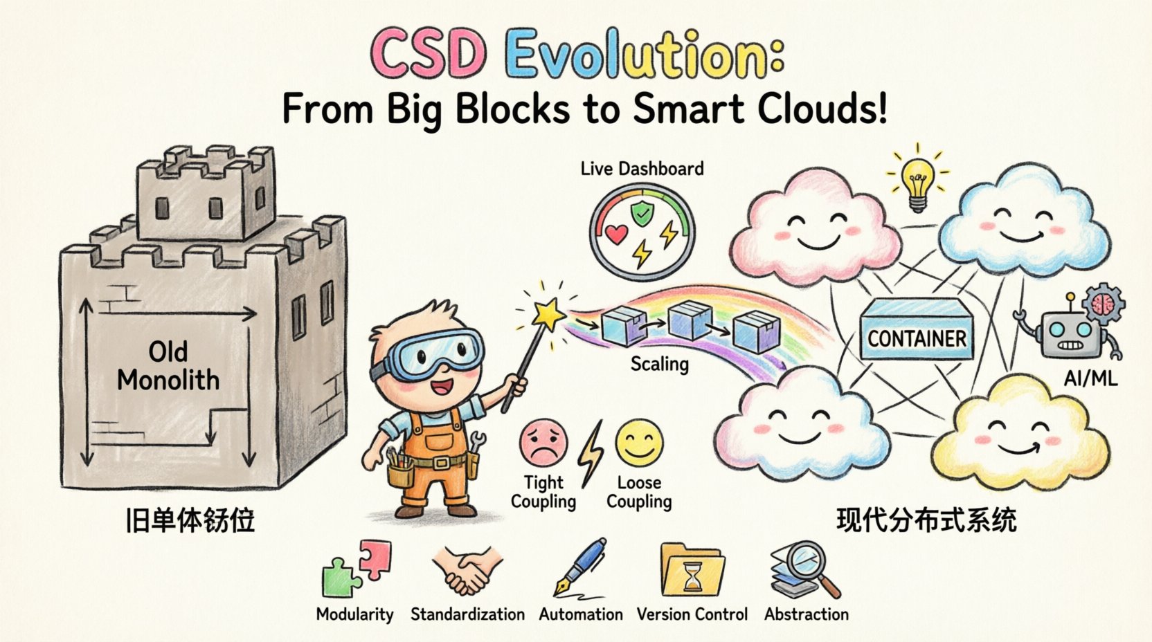
The most significant driver for the evolution of CSDs is the move away from monolithic structures. In a monolith, a single process contains all logic. In a distributed system, logic is fragmented across services, containers, and edge devices. The Composite Structure Diagram must now represent these boundaries without becoming illegible.
1. Redefining Parts and Partitions
Historically, a Part in a CSD referred to an instance of a class within another class. In modern contexts, a Part often represents a microservice, a container instance, or a specific function within a serverless environment. The diagram must distinguish between:
- Logical Parts: The software component itself.
- Physical Parts: The hardware or runtime environment hosting the component.
Architects are beginning to hybridize these views. A single CSD might show the logical API gateway, but the partition containing it represents a Kubernetes cluster node. This dual-layer modeling helps teams understand both the code structure and the infrastructure constraints.
2. Interface Contracts in Service Meshes
Communication between parts in a modern system is rarely direct function calls. It is usually via API calls, message queues, or event streams. The interfaces in a CSD are evolving to reflect these protocols.
Key considerations include:
- Protocol Specificity: Moving beyond generic interfaces to specify HTTP/REST, gRPC, or MQTT.
- Latency Constraints: Annotating interfaces with expected response times or throughput limits.
- Security Boundaries: Defining authentication requirements at the port level.
Cloud-Native and Containerized Environments ☁️
Containerization has decoupled the application from the underlying operating system. This decoupling changes how we model structure. A Composite Structure Diagram that depicts a single binary is now obsolete. It must depict a collection of containers orchestrated together.
Dynamic Scaling Representation
Static diagrams struggle to show scaling. A CSD for a modern system often needs to indicate:
- Which parts are stateless and can be replicated.
- Which parts require affinity to specific nodes.
- How parts interact during load balancing events.
To address this, future modeling standards are incorporating annotations that describe scaling policies. For example, a partition might be marked with a cardinality constraint indicating that three instances must exist simultaneously for redundancy.
Infrastructure as Code (IaC) Integration
There is a growing convergence between modeling diagrams and Infrastructure as Code definitions. While CSDs remain visual abstractions, the underlying data is increasingly machine-readable. This allows the diagram to serve as a source of truth for deployment scripts. The evolution here is not just visual, but functional.
Artificial Intelligence and Data Processing Nodes 🤖
The integration of AI and Machine Learning models into application structures introduces new structural elements. A CSD must now accommodate:
- Model Artifacts: Representing the trained model as a distinct part.
- Data Pipelines: Showing the flow of data from ingestion to inference.
- Compute Resources: Distinguishing between CPU-bound and GPU-bound parts.
When a system relies on a neural network, the structure of the data processing pipeline is as important as the business logic. The CSD provides the map for this pipeline. It defines where the data enters, how it is transformed, and where the result is returned.
Key Modeling Considerations for AI:
- Input/Output Ports: Clearly defined tensors or data schemas.
- Compute Nodes: Explicit labeling of hardware requirements.
- State Management: Distinguishing between ephemeral inference and persistent model storage.
Runtime vs. Design Time Modeling ⏱️
One of the biggest challenges in modern modeling is the gap between design time and runtime. A diagram created during the design phase may not match the runtime topology due to dynamic provisioning or service discovery. The future of CSDs lies in bridging this gap.
Live Visualization
Advanced tools are moving toward live CSDs that pull data from the runtime environment. This means the diagram is not a static document but a dashboard. It reflects the current state of the system.
- Health Status: Colors or icons indicating the health of each part.
- Dependency Mapping: Showing active connections between services in real-time.
- Configuration Drift: Highlighting differences between the model and the actual deployment.
Continuous Verification
As systems evolve, the diagram must evolve. Continuous Integration and Continuous Deployment (CI/CD) pipelines can be configured to validate the CSD against the codebase. If a service is removed or a new interface is added, the diagram generation process flags the discrepancy. This ensures documentation remains accurate without manual overhead.
Interoperability and Standardization 🤝
As tools proliferate, interoperability becomes a concern. Different teams may use different modeling languages or extensions. The future outlook emphasizes standardization to ensure CSDs are universally understood.
Unified Modeling Language (UML) Extensions
The UML standard is being extended to better support cloud and IoT. Profiles are being developed to add specific stereotypes for cloud resources. This allows a CSD to be more specific without losing its general applicability.
Data Exchange Formats
To facilitate automation, the data within the diagram is often stored in formats like XMI or JSON. This allows other systems to parse the structure and generate documentation, tests, or configuration files automatically.
Challenges in Modern CSD Modeling 🛑
Despite the benefits, evolving these diagrams comes with difficulties. Architects must navigate several pitfalls.
1. Complexity Overload
As systems grow, the CSD can become cluttered. Showing every microservice and interface in a single diagram is impossible. The challenge is abstraction. How do you show the whole system without overwhelming the reader?
- Solution: Hierarchical nesting. Use a high-level view that drills down into specific sub-structures.
- Solution: Views and viewpoints. Create specific diagrams for security, performance, and logic.
2. Abstraction vs. Reality
Diagrams are abstractions. They simplify reality. In high-frequency trading or critical infrastructure, too much simplification can hide risks. The model must be detailed enough to be useful but simple enough to be understood.
3. Maintenance Burden
If a diagram is not updated, it becomes a liability. Teams often abandon modeling because the effort to update it exceeds the value it provides. Automation is the only sustainable path forward.
Comparison: Traditional vs. Modern CSD Usage 📊
To clarify the shift, here is a comparison of how Composite Structure Diagrams are utilized in legacy versus modern contexts.
| Feature | Traditional CSD | Modern CSD |
|---|---|---|
| Primary Focus | Class hierarchy and internal logic | Service boundaries and runtime topology |
| Deployment Context | Single server or process | Distributed cloud infrastructure |
| Communication | Direct method calls | APIs, Events, Message Queues |
| Update Frequency | Release cycle | Continuous / Real-time |
| Tooling | Static design tools | Integrated DevOps platforms |
| Interface Detail | Method signatures | Protocol, Schema, Security Constraints |
Best Practices for Future-Proofing Models 🚀
To ensure Composite Structure Diagrams remain relevant, teams should adopt specific practices.
- Modularity: Break large systems into manageable sub-structures. Do not attempt to model the entire enterprise in one view.
- Standardization: Agree on naming conventions for parts and interfaces across all teams.
- Automation: Use scripts to generate diagrams from code repositories or IaC files.
- Version Control: Store diagram definitions in the same repository as the code to track changes.
- Abstraction Layers: Maintain multiple levels of detail. A high-level view for management and a detailed view for engineers.
FAQ: Common Questions on CSD Evolution ❓
Do I still need Composite Structure Diagrams?
Yes, but the scope has changed. They are no longer just for class structure. They are now essential for understanding distributed system boundaries and data flow between services.
How do I handle dynamic scaling in a static diagram?
Use annotations or metadata to indicate scaling policies. For example, mark a partition as “Auto-Scaling” with a defined range. This communicates intent without requiring a dynamic diagram.
Can CSDs replace architecture diagrams?
No. CSDs focus on internal structure. Architecture diagrams (like C4 or Deployment diagrams) focus on high-level connectivity. They complement each other.
What tools should I use?
Choose tools that support API integration and allow for custom extensions. The goal is to integrate modeling into your workflow, not treat it as a separate task.
Is UML still relevant?
UML remains a foundational standard. While specific profiles evolve, the core concepts of parts, roles, and interfaces remain valid for describing system structure.
Final Thoughts on Structural Modeling 🧭
The evolution of Composite Structure Diagrams mirrors the evolution of software itself. We have moved from simple, contained processes to complex, distributed networks. The diagram must reflect this complexity without becoming a barrier to understanding.
By focusing on automation, standardization, and dynamic representation, teams can keep these models useful. The goal is not to create pretty pictures, but to create accurate maps of the system. These maps guide development, identify risks, and facilitate communication. As systems continue to grow, the need for precise structural documentation will only increase.
Architects and developers who embrace this evolution will find their documentation becomes a living asset rather than a static artifact. This shift ensures that the structure of the code remains aligned with the structure of the documentation, reducing drift and improving system reliability.
The future is not about replacing these diagrams but enhancing them. With better integration and smarter modeling, Composite Structure Diagrams will continue to be a vital tool for navigating the complexities of modern technology.