


Software systems evolve. Requirements shift, technologies change, and business logic adapts. A critical factor in managing this evolution is the initial quality of the architectural documentation. Among the various modeling techniques available, the Composite Structure Diagram (CSD) offers a granular view of the internal composition of a classifier. By focusing on the internal structure of a system component, developers can create blueprints that facilitate long-term stability. This guide explores how to leverage the Composite Structure Diagram to ensure maintainability throughout the software lifecycle.
🔍 Understanding the Composite Structure Diagram
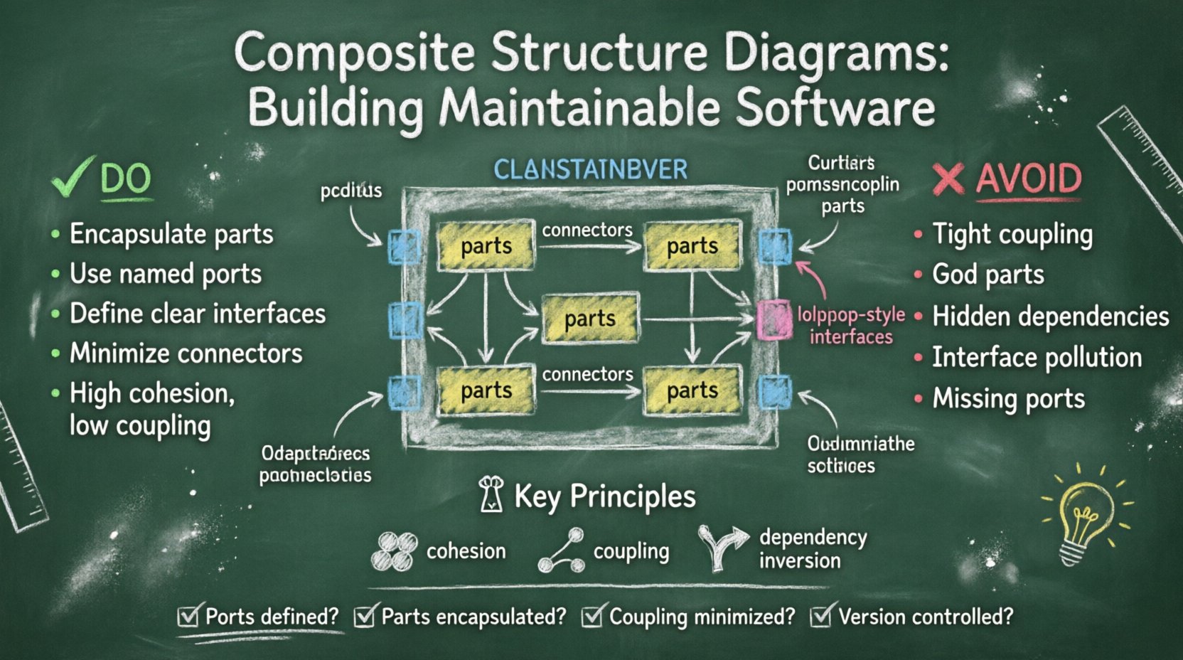
A Composite Structure Diagram is a specialized type of UML diagram that describes the internal structure of a classifier. Unlike a Class Diagram, which shows static relationships between classes, a CSD illustrates the internal parts, ports, and connectors that make up a specific component. This level of detail is essential for understanding how data flows within a complex system.
- Classifier: The top-level element being modeled, such as a class or component.
- Part: Instances of other classifiers contained within the composite structure.
- Port: A point of interaction where a part connects to the outside world.
- Interface: Defines the contract of operations available at a port.
- Connector: Establishes a physical or logical link between ports or parts.
When designed correctly, these diagrams serve as a contract between different teams. They clarify dependencies, reduce ambiguity, and provide a clear map for future modifications. Without this internal visibility, maintenance often becomes a process of trial and error, leading to technical debt.
🧱 Core Components for Maintainability
Each element within a Composite Structure Diagram plays a specific role in maintaining system integrity. To ensure the diagram supports future changes, each component must be defined with precision and clarity.
1. Parts and Encapsulation
Parts represent the building blocks inside a composite structure. When modeling parts, it is vital to respect encapsulation principles. A part should not expose its internal state to other parts unless explicitly defined through interfaces.
- Visibility Control: Use appropriate visibility modifiers (private, protected, public) to restrict access.
- Encapsulation: Keep data modifications internal to the part to prevent unintended side effects.
- Granularity: Avoid making parts too large; small, focused parts are easier to replace or upgrade.
2. Ports and Interaction Points
Ports are the gateways through which a composite structure communicates. They define the boundary of interaction. Proper use of ports is one of the most effective ways to reduce coupling.
- Named vs. Anonymous: Named ports provide clarity in documentation, making it easier to trace connections.
- Required vs. Provided: Clearly distinguish between what the system needs and what it offers to others.
- Interface Implementation: Ensure every port has a defined interface contract to prevent runtime errors.
3. Connectors and Data Flow
Connectors link parts together. They represent the physical or logical pathways for data and control signals. Poorly designed connectors can create tight dependencies that make refactoring difficult.
- Type Safety: Connectors should enforce type compatibility between interacting parts.
- Directionality: Clearly indicate the flow of data to avoid circular dependencies.
- Optimization: Minimize the number of connectors to reduce complexity and potential failure points.
🛠️ Architectural Principles for Longevity
Designing a maintainable diagram requires adherence to established software engineering principles. These principles guide decisions regarding structure, interaction, and documentation.
Cohesion and Coupling
Cohesion refers to how closely related the responsibilities of a part are. High cohesion means a part does one thing well. Coupling refers to the degree of interdependence between software modules. Low coupling is the goal.
- High Cohesion: Group related functionality within a single part. This makes the part easier to understand and modify.
- Low Coupling: Minimize dependencies between parts. If one part changes, the impact on others should be negligible.
- Interface Segregation: Ensure interfaces are specific to the needs of the consumer. Do not force a part to implement methods it does not use.
Dependency Management
Dependencies are the lifeblood of a system, but they can also be a source of fragility. The Composite Structure Diagram allows for explicit visualization of these dependencies.
- Dependency Inversion: Depend on abstractions (interfaces) rather than concrete implementations.
- Isolation: Isolate external dependencies behind ports to allow for easier swapping of underlying technologies.
- Explicit Contracts: Define all dependencies explicitly in the diagram to prevent hidden assumptions.
📉 Common Structural Anti-Patterns
Even experienced architects can fall into traps that compromise maintainability. Recognizing these patterns early allows teams to correct course before implementation begins. The following table outlines common issues and their recommended solutions.
| Anti-Pattern | Impact on Maintainability | Recommended Practice |
|---|---|---|
| Tight Coupling | Changes in one part break others. | Use interfaces to decouple parts. |
| God Parts | Single parts become too complex to manage. | Split large parts into smaller, focused components. |
| Hidden Dependencies | Unseen links cause unexpected failures. | Document all connections explicitly with connectors. |
| Interface Pollution | Interfaces become bloated and confusing. | Use specific interfaces for specific consumer needs. |
| Missing Ports | Direct access to internal state violates encapsulation. | Define ports for all external interactions. |
📝 Documentation and Version Control
A diagram is only useful if it remains accurate over time. Maintaining the synchronization between the diagram and the actual codebase is a continuous process.
Integration with Source Code
When possible, link the diagram directly to the source code. This ensures that the documentation evolves alongside the product.
- Code Generation: Use tools that can generate diagrams from existing code to keep them current.
- Reverse Engineering: Regularly regenerate diagrams from the codebase to identify drift.
- Comments: Place documentation comments in the code that reference specific parts of the diagram.
Versioning Strategies
As the system grows, the diagram will grow with it. Version control for diagrams is just as important as version control for code.
- Change Logs: Record every modification to the diagram structure.
- Branching: Maintain branches for different architectural versions to compare impacts.
- Approval Workflows: Require review before major structural changes are committed.
🔄 Impact Analysis and Refactoring
One of the primary benefits of a well-documented Composite Structure Diagram is the ability to perform impact analysis. When a requirement changes, the diagram helps visualize which parts will be affected.
Tracing Dependencies
When modifying a part, trace the connectors to identify all dependent components. This prevents the “butterfly effect” where a small change causes widespread failure.
- Upstream Analysis: Check if the change affects parts that provide data to the modified component.
- Downstream Analysis: Check if the change affects parts that consume data from the modified component.
- Side Effects: Look for shared resources that might be impacted by the change.
Refactoring Steps
Refactoring should follow a structured approach to minimize risk.
- Identify the Goal: Define what structural improvement is needed.
- Update the Diagram: Model the change in the diagram before touching code.
- Simulate: Verify the new structure does not introduce new dependencies.
- Implement: Apply the changes to the codebase.
- Verify: Test the system to ensure the new structure behaves as expected.
🤝 Collaboration and Communication
Diagrams are not just technical artifacts; they are communication tools. They bridge the gap between developers, architects, and stakeholders.
Clarity for Stakeholders
Stakeholders need to understand the system’s structure to make informed decisions. A clear CSD helps non-technical participants grasp the complexity of the system.
- Abstraction Levels: Provide high-level views for executives and detailed views for engineers.
- Consistent Notation: Use standard symbols to ensure universal understanding.
- Legend: Include a legend for complex diagrams to explain custom symbols.
Team Alignment
Development teams need to agree on the structure to avoid conflicting implementations. The diagram serves as the single source of truth.
- Shared Vocabulary: Agree on the names of parts, ports, and interfaces.
- Design Reviews: Conduct regular reviews of the diagram to ensure alignment.
- Onboarding: Use the diagram as a primary resource for new team members.
🚀 Future Proofing the Design
Anticipating future needs is a key aspect of maintainability. While you cannot predict every change, you can design structures that accommodate flexibility.
Extensibility
Design parts that can be extended without modification. This follows the Open/Closed Principle.
- Inheritance: Use inheritance hierarchies to share common behavior.
- Composition: Prefer composition over inheritance for more flexible relationships.
- Strategy Patterns: Use interfaces to allow different behaviors to be swapped at runtime.
Scalability
The structure should support growth in terms of load and complexity.
- Partitioning: Divide large components into smaller subsystems.
- Load Balancing: Model how multiple instances of a part interact.
- Resource Management: Clearly define how resources are allocated and released.
📋 Checklist for Maintainable Design
Before finalizing a Composite Structure Diagram, review the following checklist to ensure the design supports long-term maintenance.
- ☑ Are all ports explicitly defined with interfaces?
- ☑ Are parts encapsulated and not exposing internal state?
- ☑ Is coupling between parts minimized?
- ☑ Are connectors labeled to indicate data flow direction?
- ☑ Is the diagram versioned and tracked?
- ☑ Are there clear guidelines for extending the structure?
- ☑ Is the notation consistent across the entire system?
- ☑ Have stakeholders reviewed and approved the structure?
🔗 The Path Forward
Building software is an iterative process, but the foundation must be solid. The Composite Structure Diagram provides the necessary detail to understand the internal mechanics of a system. By focusing on parts, ports, interfaces, and connectors, architects can create designs that are resilient to change.
Maintainability is not an afterthought; it is a result of deliberate design choices. When teams prioritize clear structure and explicit contracts in their diagrams, they reduce the cost of future modifications. This approach leads to systems that are easier to test, debug, and extend. The effort invested in proper diagram design pays dividends throughout the entire lifespan of the software.
Start by auditing existing diagrams for coupling and clarity. Update them to reflect current best practices. Ensure that every new component follows the established patterns. Over time, these habits will create a culture of quality and stability. The goal is not perfection, but progress. By continuously refining the structural documentation, teams ensure their systems remain adaptable and robust in the face of evolving demands.