


Transitioning from textual requirements to visual models is one of the most critical skills in system design. It bridges the gap between what a stakeholder wants and what the system actually does. Among the various modeling techniques available, the Composite Structure Diagram offers a unique perspective. It dives deeper than a standard class diagram by showing the internal structure of classifiers and how they interact with their environment.
This guide focuses on constructing Composite Structure Diagrams from scratch. We will move logically from raw requirement text to a structured visual representation. The goal is clarity, precision, and maintainability.
1. Understanding the Input: Requirements Analysis 📝
Before drawing a single line, you must understand what you are building. A Composite Structure Diagram is not a creative exercise; it is a technical specification. The foundation lies in the requirements document.
Functional vs. Non-Functional Requirements
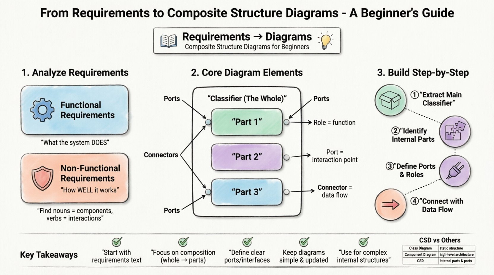
- Functional Requirements: These describe specific behaviors or functions. For example, “The system shall validate user credentials before granting access.” This dictates the logic inside a component.
- Non-Functional Requirements: These describe constraints like performance, security, or reliability. For example, “The system must handle 1,000 concurrent connections.” This often influences the structural composition, such as adding load balancers or redundant parts.
Identifying the System Boundary
Every diagram needs a context. You must define what is inside the system and what is outside. This boundary determines which parts become Parts in your diagram and which become external Roles.
When analyzing requirements, look for nouns. Nouns often represent classes, objects, or components. Verbs represent interactions or methods. In the context of a Composite Structure Diagram, focus on the nouns that are composed of other parts.
2. Anatomy of a Composite Structure Diagram 🔬
A Composite Structure Diagram shows the internal structure of a classifier. It reveals the parts that make up the whole and how they are wired together. To build this effectively, you need to understand the core elements.
Core Elements
- Classifier: The main entity being modeled. This is the “whole” in the composite pattern.
- Part: A component or object that is contained within the classifier. Parts define the internal makeup.
- Role: The function a part serves. A single part might play multiple roles within the system.
- Port: A named interaction point on a classifier. Ports define how a classifier interacts with its environment or internal parts.
- Connector: A line that links a Port to a Role, or a Port to another Port. This represents the flow of data or control.
- Internal Block: The diagram itself is often referred to as an internal block diagram in modern contexts.
Interfaces and Realization
Interfaces are crucial for decoupling. They define a contract of behavior without specifying implementation. In a Composite Structure Diagram, parts often realize interfaces. This allows the internal structure to change without affecting the external contracts.
3. Step-by-Step Walkthrough: From Text to Visual 🚀
Let us apply this knowledge to a practical scenario. Imagine a requirement to build a “Smart Home Security System.” We will walk through the process of converting this text into a structural diagram.
Step 1: Extract the Main Classifier
Identify the primary system. In this case, it is the Security System Controller. This will be the large box representing the composite classifier.
Step 2: Identify Internal Parts
Read the requirements for sub-components. The system requires a Camera Module, a Motion Sensor, and a Notification Service. These become the Parts inside the main classifier.
- Part 1: Camera Module (Type: VideoCapture)
- Part 2: Motion Sensor (Type: MotionDetector)
- Part 3: Notification Service (Type: AlertSender)
Step 3: Define Roles and Ports
How do these parts communicate? They need specific points of interaction.
- The Camera Module has a port for VideoStream.
- The Motion Sensor has a port for MotionEvent.
- The Notification Service has a port for AlertMessage.
The main Security System Controller needs ports to interact with the outside world, such as a UserInterface port and a CloudSync port.
Step 4: Connect the Parts
Draw lines (connectors) between the ports of the internal parts and the roles they fulfill. For instance, the Camera Module might feed data into the Notification Service when motion is detected.
Ensure every connection has a clear direction. Use arrows to indicate data flow. This step transforms a list of components into a functioning architecture.
4. The Composite Pattern in Modeling 🧩
The Composite Structure Diagram is heavily influenced by the Composite Design Pattern. This pattern allows you to treat individual objects and compositions of objects uniformly. Understanding this pattern is key to creating scalable models.
Leaf vs. Composite
- Leaf Objects: These are the base units. They do not contain other parts. Examples include a simple sensor or a basic button.
- Composite Objects: These contain other parts. They act as containers. The Security System Controller is a composite object.
Recursive Structure
A composite can contain other composites. This creates a hierarchy. For example, a Zone might be a composite that contains multiple Sensors. The Security System Controller then contains multiple Zones.
When modeling this:
- Draw the outer box for the Zone.
- Draw the inner boxes for the Sensors inside the Zone.
- Draw the Zone inside the Controller.
This recursive nature helps in managing complexity. You can hide the details of a Zone when looking at the Controller level, focusing only on the interface.
5. Comparison: CSD vs. Other Diagrams 📊
It is easy to confuse the Composite Structure Diagram with other UML diagrams. Knowing when to use which one is vital for maintaining documentation quality.
| Diagram Type | Primary Focus | Best Used For |
|---|---|---|
| Composite Structure Diagram | Internal structure of a classifier | Showing composition of parts, ports, and roles |
| Class Diagram | Static structure and relationships | Defining attributes, methods, and general associations |
| Component Diagram | High-level software components | System architecture and deployment boundaries |
| Deployment Diagram | Hardware and runtime environment | Physical nodes, servers, and network topology |
Use the Composite Structure Diagram when you need to see inside a specific class or component. Do not use it for high-level system architecture or database schemas.
6. Common Pitfalls to Avoid ⚠️
Even experienced modelers make mistakes. Being aware of common errors saves time during the review process.
Overcomplicating the Diagram
Do not try to show every single method or variable. The purpose is structural. If a part is too complex, consider creating a separate diagram for its internal structure. Clarity is more important than completeness.
Ignoring Ports
Skipping ports leads to ambiguous connections. Without ports, it is unclear where the data enters or exits a part. Always define ports explicitly.
Mixing Levels of Abstraction
Do not mix logical parts with physical nodes. For example, do not show a specific database server inside a software component unless you are modeling the deployment. Keep the logical structure separate from the physical infrastructure.
Unclear Roles
A role describes what a part does, not what it is. Ensure the role name reflects the interaction (e.g., DataProvider) rather than the type (e.g., Database). This allows you to swap the underlying implementation without changing the diagram.
7. Best Practices for Maintenance 🛠️
Diagrams are living documents. They require updates as the system evolves. Follow these practices to keep your models useful.
- Keep it Updated: If the code changes, update the diagram. An outdated diagram is worse than no diagram.
- Use Naming Conventions: Stick to a consistent naming style for parts and ports. This reduces cognitive load.
- Group Related Parts: Use grouping boxes or frames to organize parts that belong to a specific subsystem.
- Document Interfaces: Clearly document the interface contracts that ports rely on. This ensures developers know the expected behavior.
- Limit Depth: Avoid nesting composites too deeply. Three levels of depth is usually the maximum recommended for readability.
8. Advanced Concepts: Delegation and Constraints 🧠
Beyond the basics, there are advanced features that add precision to your models.
Delegation Connectors
Delegation allows a part of a composite to forward requests to another part. For example, the Controller might delegate a Login request to a specific Authentication Part. This is represented by a specific connector type that shows the request passing through the composite to the internal part.
Constraints
Constraints define rules that must be met. These are often written in a constraint language or plain text within a note attached to a part or connector.
- Timing Constraints: “The response must occur within 200ms.”
- Resource Constraints: “The part must not consume more than 5MB of memory.”
- Logic Constraints: “The sensor must be active before the camera starts.”
Placing these constraints directly on the diagram helps developers understand the non-functional requirements at a glance.
9. Practical Example: IoT Device Architecture 🌐
Let us expand the previous example into a more complex scenario: an IoT Weather Station.
Requirements Summary
- Collect temperature and humidity data.
- Store data locally.
- Transmit data to a cloud server.
- Display data on a local screen.
Diagram Structure
Classifier: WeatherStationController
Internal Parts:
- TemperatureSensor (Port: TempData)
- HumiditySensor (Port: HumData)
- LocalStorage (Port: DataStore)
- CloudClient (Port: UploadLink)
- DisplayUnit (Port: VisualOutput)
Connectors:
- TemperatureSensor → LocalStorage
- HumiditySensor → LocalStorage
- LocalStorage → CloudClient (Triggered by schedule)
- LocalStorage → DisplayUnit (Triggered by user request)
This structure clearly separates the concerns. The sensors gather data, storage manages it, and the other parts handle transmission and display. If you need to change the cloud provider, you only update the CloudClient part, not the whole diagram.
10. Final Thoughts on Structural Modeling 💡
Creating a Composite Structure Diagram is about understanding the composition of your system. It requires a shift in mindset from thinking about functions to thinking about containers and contents. By adhering to the steps outlined above, you can produce models that are both technically accurate and easy to understand.
Remember that diagrams are communication tools. They exist to help teams understand the system architecture. If a diagram confuses the reader, it has failed its purpose. Prioritize simplicity and clarity over complexity.
As you practice, you will find that the transition from requirements to diagrams becomes more intuitive. Start with small components, define their parts clearly, and gradually build up to the full system. This methodical approach ensures a solid foundation for your design.
FAQ: Frequently Asked Questions ❓
What is the difference between a composite and an aggregation?
In structural modeling, composition implies a stronger lifecycle dependency. If the whole dies, the parts die. Aggregation implies a weaker relationship where parts can exist independently. The diagram symbols differ slightly, but the context defines the relationship.
Can I use this for software architecture?
Yes. It is particularly useful for object-oriented software design where objects are composed of other objects. It helps visualize the internal logic of complex classes.
How detailed should the diagram be?
It depends on the audience. For developers, include ports and roles. For stakeholders, focus on the high-level parts and their interactions. Avoid showing every single attribute.
Is this diagram mandatory for every project?
No. It is used when the internal structure of a component is complex enough to warrant a separate view. For simple systems, a standard class diagram may suffice.
What if I need to change the parts later?
Because the diagram focuses on interfaces and ports, you can swap out parts as long as they realize the same roles. This makes the model flexible for refactoring.
Summary of Key Takeaways ✅
- Start with Requirements: Always derive the structure from the text first.
- Focus on Composition: Identify the parts that make up the whole.
- Define Interfaces: Use ports and roles to manage interactions.
- Maintain Clarity: Avoid over-complicating the visual representation.
- Keep it Updated: Ensure the model reflects the current state of the design.
By following these guidelines, you will create robust, maintainable, and clear Composite Structure Diagrams. This skill adds significant value to any technical team, ensuring that the vision from the requirements phase translates accurately into the final implementation.