


Understanding the internal architecture of a system is crucial for any software architect. While standard class diagrams show relationships between objects, they often fail to capture the internal composition of a single class or component. This is where the Composite Structure Diagram shines. It offers a granular view of how a classifier is constructed from internal parts. 🧩
For architects beginning their journey into detailed system modeling, mastering this notation provides a deeper insight into complexity management. This guide explores the anatomy, usage, and best practices of the Composite Structure Diagram without relying on specific tools or hype. We will focus on the structural integrity and logical flow of design.
What is a Composite Structure Diagram? 🤔
A Composite Structure Diagram is a type of diagram in the Unified Modeling Language (UML). It describes the internal structure of a classifier, such as a class or component. It shows the parts that make up the whole and the roles these parts play within the system.
Unlike a class diagram, which focuses on external relationships, this diagram focuses on the internal arrangement. It answers questions like:
- What pieces constitute this module?
- How do these pieces interact internally?
- Which interfaces does this component expose to the outside world?
- How are resources managed within the boundary of this structure?
This level of detail is essential for microservices, complex object-oriented systems, and hardware-software integration projects.
Core Elements and Notation 🛠️
To create a clear and effective diagram, you must understand the building blocks. Each element serves a specific purpose in defining the internal logic.
1. The Classifier (The Container) 📦
The main box represents the classifier being analyzed. It has a header containing the name of the class or component. The body of the box is partitioned to show internal parts.
- Header: Displays the name of the composite structure.
- Body: Contains the internal parts, ports, and connectors.
2. Parts (Internal Components) 🔗
Parts are the objects that make up the composite structure. They are displayed as rectangles within the main classifier box.
- Type: Every part must have a type, which can be a class, interface, or component.
- Multiplicity: Indicated as
[1..*]or similar, showing how many instances of the part exist within the composite. - Name: An optional identifier for the specific instance of the part.
3. Ports (Interaction Points) 🚪
Ports are the interaction points where the internal parts connect with the external environment or other internal parts. They define the contract of communication.
- Provided Interfaces: Represented by a lollipop symbol (circle with a line).
- Required Interfaces: Represented by a half-circle symbol (socket).
4. Connectors (Links) 🔌
Connectors establish communication between ports. They can link:
- Internal parts to internal parts.
- Internal parts to external ports.
- Ports to other external elements.
These links represent the flow of data or control signals within the structure.
5. Delegation Connectors 🔄
A delegation connector connects a port on the composite structure to a port on an internal part. It effectively delegates a request from the outside interface to the internal component responsible for handling it.
Visualizing the Internal Structure 📊
When drawing these diagrams, layout matters. A chaotic diagram obscures logic. A structured diagram reveals intent.
Consider the following breakdown of how to organize the information visually:
| Element | Symbol Description | Function |
|---|---|---|
| Classifier | Rectangular box with title bar | Defines the scope of the composite structure |
| Part | Rectangle inside the classifier | Represents an internal instance of a type |
| Port | Small square or rectangle on the border or inside | Defines an interaction point (interface) |
| Connector | Line connecting two elements | Shows the relationship or data flow |
| Interface | Lollipop or Socket symbol | Defines the contract for communication |
Distinguishing from Class Diagrams 📝
It is common to confuse this diagram with a standard Class Diagram. While both deal with classes, their focus differs significantly.
- Class Diagram: Focuses on static relationships between classes (inheritance, association, aggregation). It shows the system from the outside.
- Composite Structure Diagram: Focuses on the internal anatomy of a single class. It shows the system from the inside.
Using a Composite Structure Diagram allows architects to drill down into a specific component without cluttering the high-level class diagram. It isolates complexity.
When to Use This Diagram 🕒
Not every class needs a composite structure view. Use it when:
- Complexity is High: A class has many internal dependencies.
- Resource Management: You need to show how resources (like threads or memory buffers) are allocated internally.
- Interface Delegation: You need to clarify how an external request reaches a specific internal handler.
- Hardware Integration: You are modeling how software maps to physical components.
- Refactoring: You are planning a change in the internal architecture and need to visualize the impact.
Step-by-Step Guide to Creating a Diagram 📐
Follow this logical flow to construct a robust diagram.
Step 1: Define the Classifier
Start with the main box. Give it a clear name. Identify the primary responsibility of this structure. Is it a Controller? A Manager? A Processor?
Step 2: Identify Internal Parts
List the objects that reside inside this classifier. These are the parts. For each part, define its type. If a part is a database connection, the type is ConnectionPool. If it is a logger, the type is Logger.
Step 3: Assign Roles
Each part plays a role within the structure. A part might be a Reader in one context and a Writer in another. Explicitly label these roles if they differ from the type name.
Step 4: Define Ports
Where does this structure talk to the outside? Create ports for those interactions. Specify the interface type for each port. Does it require a specific API? Does it provide a specific service?
Step 5: Draw Connectors
Link the parts to the ports. If a part handles a specific interface, draw a line from the part to the port. If the port is just a pass-through, use a delegation connector to link the external port to the internal part.
Step 6: Review Multiplicity
Check the cardinality. Is there exactly one instance of this part? Or many? Add multiplicity constraints to ensure the model reflects the runtime reality.
Advanced Concepts: Collaboration and Node 🧠
Beyond the basics, there are advanced concepts that add precision to your modeling.
Collaboration
A collaboration represents a set of interacting classifiers. In a composite structure diagram, you can show how the internal parts collaborate to fulfill the responsibilities of the main classifier. This is often visualized by grouping parts and showing the flow between them.
Node
When the composite structure represents a deployment unit or a physical device, the diagram can be viewed as a Node. This bridges the gap between logical design and physical deployment.
Best Practices for Clarity ✅
To ensure the diagram remains a useful tool rather than a source of confusion, adhere to these guidelines.
- Keep it Focused: Do not try to model the entire system in one diagram. Focus on one classifier at a time.
- Use Consistent Naming: Ensure part names and type names follow a standard convention.
- Minimize Crossing Lines: Arrange parts to reduce the number of connectors that cross each other. This improves readability.
- Leverage Layers: Use layers to separate different concerns, such as data access, business logic, and presentation, within the same structure.
- Document Interfaces: Always document the interface types clearly. Ambiguity in interface definitions leads to implementation errors.
Common Pitfalls to Avoid ⚠️
Even experienced architects make mistakes when transitioning to this notation.
- Over-Modeling: Creating composite structures for simple classes adds noise without value. Keep it for complex entities.
- Ignoring Multiplicity: Failing to specify how many parts exist can lead to runtime errors if the architecture assumes a singleton but the design allows multiple.
- Confusing Parts with Associations: A part is owned by the composite. An association is a relationship. Do not mix these concepts.
- Neglecting Ports: If you define internal parts but do not expose them via ports, the internal structure is isolated and cannot interact with the outside world.
Integrating with System Design 🌐
This diagram does not exist in isolation. It fits into the broader system design documentation.
- Sequence Diagrams: Use sequence diagrams to show the dynamic behavior triggered by the interactions defined in the composite structure.
- Deployment Diagrams: Map the composite structures to physical nodes to understand resource allocation.
- State Machine Diagrams: If a part has complex internal states, a state machine can complement the structural view.
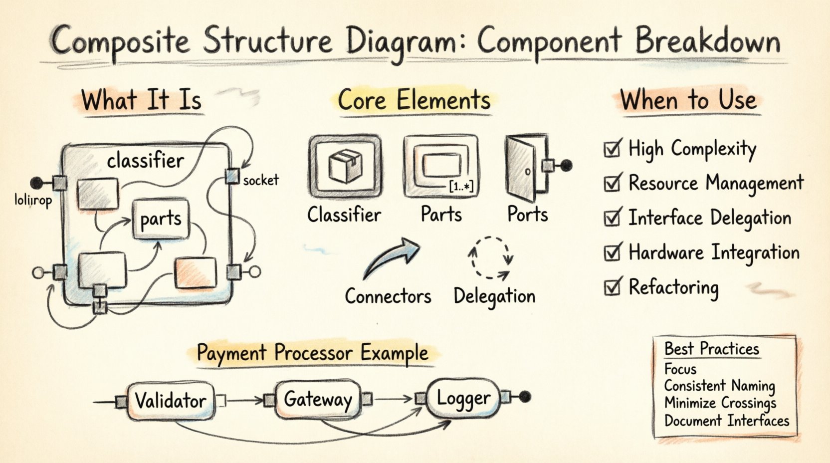
Case Study: A Payment Processing Module 💳
Let us look at a practical example. Consider a PaymentProcessor class.
External View: It accepts a transaction request and returns a status.
Internal View (Composite Structure):
- Part 1:
Validator(Type:TransactionValidator). Role: Checks format. - Part 2:
Gateway(Type:ExternalGateway). Role: Connects to bank. - Part 3:
Logger(Type:AuditLogger). Role: Records activity. - Port:
ProcessRequest(Required). Delegates toValidator. - Port:
SendToBank(Required). Delegates toGateway. - Connector: Links
ValidatortoGatewayto ensure validation happens before sending.
This breakdown makes the flow explicit. If the Gateway changes, the impact on the Validator is clear.
Refining the Architecture Over Time 🔄
Software architecture is not static. As requirements change, the composite structure evolves.
- Adding Parts: New features may require new internal components.
- Removing Ports: Deprecated interfaces should be removed from the ports list.
- Changing Interfaces: If the contract changes, update the interface type on the ports.
Regularly reviewing these diagrams ensures the documentation matches the code. This practice reduces technical debt and aids onboarding for new team members.
Conclusion on Structural Integrity 🏁
The Composite Structure Diagram is a powerful tool for defining the internal makeup of system components. It moves beyond simple associations to show composition, delegation, and internal interaction. By mastering this notation, architects can design systems that are modular, maintainable, and clear.
Focus on the parts, define the roles, and connect the ports. This approach leads to robust software architectures that stand the test of change. Use the diagram to clarify, not to complicate. Let the structure guide the implementation.
Start applying these concepts to your next project. Analyze the complex classes in your codebase. Break them down. Visualize the internal logic. This practice will deepen your understanding of system design and improve the quality of your architectural decisions.