


Introduction
In software engineering, UML (Unified Modeling Language) diagrams are indispensable tools for visualizing and designing complex systems. Among the various types of UML diagrams, Class Diagrams and Object Diagrams stand out as essential for modeling the static structure of a system. While both diagrams serve to represent the system’s architecture, they do so from different perspectives and with distinct purposes. Class Diagrams provide a blueprint of the system’s design by illustrating the classes, their attributes, methods, and the relationships between them. On the other hand, Object Diagrams offer a snapshot of the system’s state at a specific moment by depicting instances of these classes and their interactions. This article will delve into the key concepts, differences, and practical examples of Class Diagrams and Object Diagrams using Visual Paradigm, a powerful UML tool that simplifies the creation and management of these diagrams. By understanding these concepts and utilizing Visual Paradigm, you can effectively model and communicate the
Understanding Class Diagrams
What is a Class Diagram?
A Class Diagram is a static structure diagram that represents the system’s classes, their attributes, methods, and the relationships between them. It provides a blueprint of the system’s design, showing how different classes interact with each other.

Key Concepts in Class Diagrams
- Classes: Represented by rectangles divided into three parts: the class name, attributes, and methods.
- Attributes: Properties or data members of a class.
- Methods: Functions or operations that a class can perform.
- Relationships:
- Association: A general relationship between two classes.
- Aggregation: A whole-part relationship where the part can exist independently of the whole.
- Composition: A whole-part relationship where the part cannot exist independently of the whole.
- Generalization: An inheritance relationship where a subclass inherits attributes and methods from a superclass.
- Dependency: A relationship where a change in one class affects another class.
Example of a Class Diagram
Consider a simple library management system. The Class Diagram might include classes like Book, Member, and Library.
- Book: Attributes (
title,author,ISBN), Methods (checkOut,returnBook). - Member: Attributes (
name,memberID), Methods (borrowBook,returnBook). - Library: Attributes (
name,address), Methods (addBook,removeBook).
The relationships might include:
- Association:
MemberborrowsBook. - Aggregation:
LibrarycontainsBook. - Composition:
LibrarymanagesMember.
Understanding Object Diagrams
What is an Object Diagram?
An Object Diagram is a instance of a Class Diagram. It represents the instances of classes (objects) and their relationships at a specific point in time. Object Diagrams are used to visualize the state of a system at a particular moment.
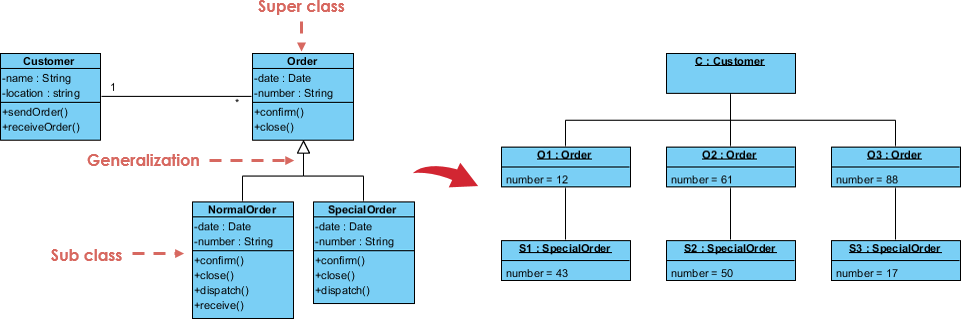
Key Concepts in Object Diagrams
- Objects: Instances of classes, represented by rectangles with the object name and class name.
- Attributes: Values of the attributes for a specific object.
- Links: Relationships between objects, similar to associations in Class Diagrams but specific to instances.
Example of an Object Diagram
Using the same library management system, an Object Diagram might show specific instances of Book, Member, and Library.
- Book: Instance (
Book1of classBookwith attributestitle = "1984",author = "George Orwell",ISBN = "9780451524935"). - Member: Instance (
Member1of classMemberwith attributesname = "John Doe",memberID = "M001"). - Library: Instance (
Library1of classLibrarywith attributesname = "City Library",address = "123 Main St").
The relationships might include:
- Link:
Member1has borrowedBook1. - Link:
Library1containsBook1.
Differences Between Class Diagrams and Object Diagrams
-
Purpose:
- Class Diagram: Shows the static structure of the system, focusing on classes and their relationships.
- Object Diagram: Shows the state of the system at a specific point in time, focusing on instances of classes and their relationships.
-
Scope:
- Class Diagram: Provides a general view of the system’s design.
- Object Diagram: Provides a specific view of the system’s state at a particular moment.
-
Level of Detail:
- Class Diagram: Includes attributes and methods of classes.
- Object Diagram: Includes attribute values and links between specific objects.
Creating Class and Object Diagrams in Visual Paradigm
Steps to Create a Class Diagram
- Open Visual Paradigm: Launch Visual Paradigm and create a new project.
- Create a Class Diagram: Select Diagram > New > Class Diagram.
- Add Classes: Use the Class tool to add classes to the diagram.
- Define Attributes and Methods: Double-click on a class to add attributes and methods.
- Establish Relationships: Use the Association, Aggregation, Composition, Generalization, and Dependency tools to define relationships between classes.
Steps to Create an Object Diagram
- Open Visual Paradigm: Launch Visual Paradigm and open the project containing your Class Diagram.
- Create an Object Diagram: Select Diagram > New > Object Diagram.
- Add Objects: Use the Object tool to add instances of classes to the diagram.
- Define Attribute Values: Double-click on an object to set the values of its attributes.
- Establish Links: Use the Link tool to define relationships between objects.
Conclusion
Class Diagrams and Object Diagrams are fundamental tools in UML for capturing the static structure of a system from different viewpoints. Class Diagrams provide a comprehensive overview of the system’s design, focusing on classes and their relationships, while Object Diagrams offer a detailed snapshot of the system’s state at a particular moment, highlighting specific instances and their interactions. Using Visual Paradigm, you can seamlessly create and manage these diagrams, enabling you to visualize and design your systems with precision and clarity. Whether you are a seasoned software engineer or a beginner in system design, mastering Class and Object Diagrams with Visual Paradigm will enhance your ability to model complex systems effectively. By leveraging these tools, you can ensure that your system designs are robust, well-documented, and aligned with your project requirements.
References
- Visual Paradigm – Class Diagram Guide
- Visual Paradigm – Object Diagram Guide
- Visual Paradigm – UML Tutorials
This comprehensive guide provides an overview of Class Diagrams and Object Diagrams, their key concepts, differences, and practical examples using Visual Paradigm. By understanding these concepts and utilizing the tools available, you can design efficient and effective UML diagrams that meet your system requirements.