


In the landscape of system architecture, clarity is often the most valuable currency. Yet, as models grow, they frequently accumulate complexity that obscures rather than reveals. The Composite Structure Diagram serves as a critical artifact for visualizing the internal structure of classifiers, revealing how parts are assembled to form a whole. However, without discipline, these diagrams can quickly become dense webs of connections that offer little insight. This guide focuses on the discipline of simplification, ensuring your diagrams remain effective tools for communication rather than artifacts of unnecessary intricacy. We will explore how to identify the signs of over-engineering and apply practical strategies to maintain structural integrity without sacrificing necessary detail.
Understanding the Role of the Composite Structure Diagram 📐
The Composite Structure Diagram is not merely a collection of boxes and lines; it is a representation of the internal organization of a classifier. It answers fundamental questions about how a system is built from the inside out. Unlike a class diagram, which focuses on static relationships between types, this diagram delves into the collaboration of internal parts, ports, and interfaces. It provides a blueprint for the internal wiring of a component, showing how data flows and how responsibilities are distributed among constituent elements.
When designing complex software systems, the temptation is to capture every conceivable interaction and dependency. While thoroughness is a virtue, excess leads to confusion. A well-constructed composite diagram should allow a developer to understand the component’s architecture at a glance. It defines the boundaries of responsibility and the mechanisms for interaction with the outside world. If a diagram requires a legend or a separate explanation to be understood, it has likely crossed the line into over-engineering.
- Focus on Internal Parts: Highlight the significant components that make up the whole.
- Define Connections: Show how parts interact via ports and interfaces.
- Clarify Boundaries: Distinguish between internal logic and external contracts.
- Minimize Abstraction: Avoid layers of indirection that do not add value.
By keeping these goals in mind, you create a model that serves the engineering team effectively. The diagram becomes a source of truth that guides implementation without imposing artificial constraints. Simplicity in modeling translates to simplicity in execution, reducing the cognitive load on everyone involved in the project.
Identifying Signs of Over-Engineering 🚩
Over-engineering in modeling often manifests as visual noise. It is not always obvious at first glance, but certain patterns emerge as complexity accumulates. Recognizing these signs early allows you to intervene before the model becomes unmanageable. It is essential to distinguish between necessary detail and decorative complexity. The former supports understanding; the latter obscures it.
Common indicators that a Composite Structure Diagram has become too complex include:
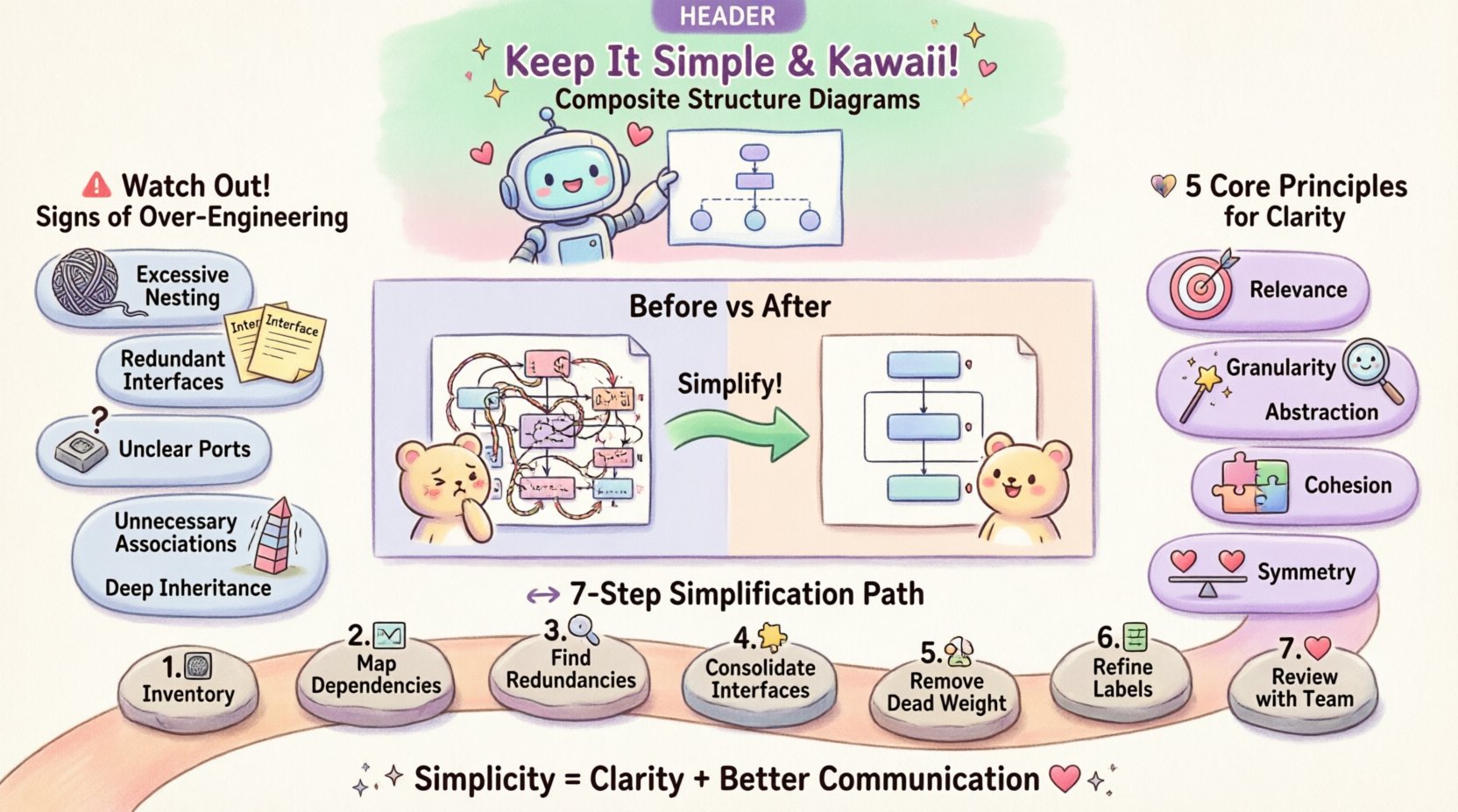
- Excessive Nesting: Components containing too many sub-components create a hierarchy that is difficult to traverse visually.
- Redundant Interfaces: Multiple interfaces performing identical functions suggest a lack of abstraction or consolidation.
- Unclear Ports: When ports are not clearly labeled or their purpose is ambiguous, the flow of information becomes speculative.
- Unnecessary Associations: Connecting parts that do not directly interact adds clutter without functional benefit.
- Deep Inheritance Chains: While not always part of the composite diagram itself, deeply nested inheritance affects the structure and should be considered during simplification.
When you encounter these symptoms, pause and evaluate the necessity of each element. Ask whether removing a specific connector or part would alter the system’s behavior. If the answer is no, the element is likely a candidate for removal. This process requires confidence in the underlying design and a willingness to trim the fat.
Core Principles for Streamlined Modeling 🧩
To maintain a lean and effective diagram, adhere to a set of core principles. These guidelines act as a filter for every decision made during the modeling process. They prioritize communication and maintainability over exhaustive documentation. The goal is to capture the essence of the structure, not every possible variation.
- Principle of Relevance: Only include elements that directly impact the understanding of the system’s behavior or structure.
- Principle of Granularity: Choose a level of detail appropriate for the audience. A high-level architectural view differs from a detailed implementation view.
- Principle of Abstraction: Hide implementation details behind clear interfaces. Show what a part does, not necessarily how it does it, unless the implementation is critical to the structure.
- Principle of Cohesion: Group related elements together. High cohesion within parts reduces the complexity of connections between them.
- Principle of Symmetry: Where possible, maintain symmetry in structure to aid pattern recognition.
Applying these principles requires a shift in mindset from “documenting everything” to “documenting what matters.” This shift reduces the maintenance burden of the diagram over time. As the system evolves, the diagram remains stable because it is built on stable, high-level concepts rather than volatile implementation details.
The Composite Pattern and Structural Clarity 🔗
The Composite Pattern is a fundamental concept in object-oriented design, and its representation in a diagram can be a source of complexity if not handled carefully. This pattern allows clients to treat individual objects and compositions of objects uniformly. In a Composite Structure Diagram, this often manifests as a recursive structure where parts contain other parts.
When modeling this pattern, it is easy to get lost in the recursion. To avoid this, focus on the structural relationship rather than the behavioral logic. Ensure that the distinction between the composite part and the leaf parts is visually distinct. Use grouping boxes to clearly separate the hierarchy levels. This visual separation helps the reader understand the containment relationship without getting bogged down in the specific attributes of every leaf node.
Consider the following strategies for modeling the Composite Pattern effectively:
- Limit Depth: Keep the nesting depth shallow. If a structure requires more than three levels of nesting, reconsider the design.
- Standardize Interfaces: Ensure that all parts expose a consistent interface to their parent. This reduces the number of distinct connection types needed in the diagram.
- Use Stereotypes: Utilize standard stereotypes to denote composite and leaf roles, reducing the need for text labels.
- Focus on Topology: Emphasize the overall shape and flow of the structure rather than the internal state of every component.
By treating the Composite Pattern as a structural tool rather than a behavioral one, you simplify the diagram. The diagram should show how the system is assembled, not necessarily every method call that occurs during execution.
A Comparison of Complexity vs. Clarity 📊
To better understand the impact of simplification, consider the following comparison between a complex, over-engineered approach and a simplified, streamlined approach. This table highlights the differences in structure, maintenance, and readability.
| Feature | Over-Engineered Approach | Simplified Approach |
|---|---|---|
| Component Count | High (many small, granular parts) | Low (consolidated, meaningful parts) |
| Connection Density | High (many cross-connections) | Low (focused, direct connections) |
| Readability | Low (requires significant time to parse) | High (understood at a glance) |
| Maintenance Effort | High (changes ripple frequently) | Low (changes are localized) |
| Communication Value | Low (confuses stakeholders) | High (aligns understanding) |
This comparison illustrates that simplicity is not about removing necessary information; it is about organizing it in a way that reduces cognitive load. The simplified approach allows stakeholders to focus on the architecture rather than the syntax.
A Step-by-Step Simplification Protocol 🔄
When reviewing an existing Composite Structure Diagram, follow this protocol to systematically reduce complexity. This process is iterative and requires careful consideration of the system’s functional requirements.
- Inventory the Elements: List all parts, ports, and interfaces currently defined in the diagram. Do not judge them yet; just record them.
- Map the Dependencies: Trace every connection to understand the data flow. Identify connections that do not contribute to the primary function.
- Identify Redundancies: Look for duplicate interfaces or parts that serve the same purpose. Merge them where appropriate.
- Consolidate Interfaces: Combine multiple small interfaces into larger, more cohesive ones if they are always used together.
- Remove Dead Weight: Eliminate parts that have no incoming or outgoing connections. These are likely artifacts of previous iterations.
- Refine Labels: Ensure all labels are concise and descriptive. Remove technical jargon that does not add semantic value.
- Review with Stakeholders: Present the simplified diagram to the team. Ask if the core structure is still clear.
This protocol ensures that simplification is not arbitrary. Each step is grounded in the functional reality of the system. By following this process, you maintain the integrity of the design while stripping away the excess.
Maintenance and Evolution 🌱
Simplification is not a one-time task; it is an ongoing practice. As systems evolve, new requirements emerge, and diagrams must adapt. However, adaptation should not mean adding complexity. Instead, it should mean finding the simplest way to accommodate new requirements.
Regular reviews of the Composite Structure Diagram are essential. Schedule periodic audits to ensure the model remains aligned with the current implementation. During these reviews, challenge every element. Ask if it is still necessary. If a part was added for a feature that was later removed, remove it from the diagram. If a connection was added for a temporary integration, verify if it is still needed.
Documentation should be treated as code. Just as you refactor code to remove technical debt, you should refactor diagrams to remove modeling debt. This mindset ensures that the visual representation of the system remains a reliable guide for the development team.
Final Thoughts on Architectural Discipline 🎯
Creating a Composite Structure Diagram is an exercise in communication. It is about conveying the internal logic of a system to others. Over-engineering undermines this purpose by introducing noise and confusion. By adhering to the principles of relevance, abstraction, and cohesion, you create diagrams that serve their intended audience.
Remember that a diagram is a tool, not a product. Its value lies in its ability to facilitate understanding and decision-making. When you prioritize simplicity, you empower your team to build better systems. The effort spent refining the diagram pays dividends in reduced miscommunication and smoother implementation. Keep the structure lean, the connections clear, and the focus sharp.