
Introduction
A class diagram is a fundamental tool in the Unified Modeling Language (UML) used to represent the static structure of a system by modeling its classes, attributes, and relationships. The provided diagram illustrates an internship management system, capturing entities like students, companies, and forms. This guide will break down the diagram, explain key concepts, and provide multiple class diagram examples .
Part 1: Understanding the Internship System Class Diagram
Overview of the Diagram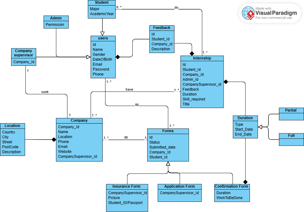
The diagram represents an internship management system with the following key entities:
- Users (abstract class): A parent class for students and admins.
- Student: A user who participates in internships and provides feedback.
- Admin: A user with specific permissions.
- Company: An entity that hosts internships and has supervisors.
- Intern: Represents the internship engagement of a student with a company.
- Feedback: Captures feedback from students about companies.
- Forms: Tracks internship-related forms (e.g., insurance, application, confirmation).
- Location: Stores address details for a company.
- Duration: Defines the internship timeline (e.g., partial or full).
Relationships in the Diagram
- Inheritance: Student and Admin inherit from Users (indicated by a hollow triangle arrow).
- Composition:
- A Company has a Location (filled diamond arrow).
- A Forms entity has a Duration (filled diamond arrow).
- Association:
- Student works at a Company (via COMPANY_SUPERVISOR).
- Student has many Intern records (1-to-many).
- Student provides Feedback about a Company.
- Company fills many Forms (1-to-many).
- Multiplicity:
- 1..*: One or more (e.g., a company fills one or more forms).
- 0..*: Zero or more (e.g., a student can have zero or more internships).
Part 2: Key Concepts of Class Diagrams
Core Components
- Class:
- Represented as a rectangle with three sections: class name, attributes, and methods (though methods are often omitted in simpler diagrams).
- Example: Student with attributes like Name, Gender, and Email.
- Attributes:
- Variables or data within a class, often with types (e.g., Name: String).
- Visibility: + (public), – (private), # (protected).
- Example: -Id: int in the Users class.
- Relationships:
- Inheritance: A subclass inherits from a superclass (e.g., Student inherits from Users).
- Association: A general relationship between classes (e.g., Student and Company).
- Composition: A strong “whole-part” relationship where the part cannot exist without the whole (e.g., Company and Location).
- Aggregation: A weaker “whole-part” relationship where the part can exist independently (not explicitly shown in this diagram but common in UML).
- Multiplicity:
- Specifies how many instances of one class can be associated with one instance of another.
- Example: 1..* means “one or more” (a company has one or more forms).
- Abstract Class:
- A class that cannot be instantiated directly (e.g., Users is abstract, as indicated by its italicized name).
Key Principles
- Abstraction: Focus on essential details, ignoring implementation specifics.
- Encapsulation: Hide internal data using visibility markers (e.g., – for private attributes).
- Modularity: Break down systems into manageable, reusable classes.
- Clarity: Ensure the diagram is easy to understand for stakeholders.
Part 3: Guidelines for Creating Effective Class Diagrams
- Define the Scope:
- Identify the system’s key entities and their relationships before diagramming.
- Example: For the internship system, focus on students, companies, and internships.
- Use Consistent Naming:
- Use clear, meaningful names for classes and attributes (e.g., Student instead of S).
- Follow naming conventions (e.g., singular nouns for classes: Company, not Companies).
- Specify Visibility:
- Indicate whether attributes are public (+), private (–), or protected (#).
- Limit Complexity:
- Avoid overcrowding by breaking large systems into smaller diagrams.
- Example: Separate user management from form management if needed.
- Validate Relationships:
- Ensure relationships reflect real-world logic (e.g., a student can only intern at one company at a time).
- Use Multiplicity:
- Clearly define how many instances are involved in relationships (e.g., 1..* for one or more).
Example 1: Basic Student and Company Relationship
This example focuses on the core relationship between Student and Company.
- Explanation:
- Student and Company are connected via an association (works_at).
- A student works at one or more companies (1..*).
Example 2: Adding Inheritance with Users
This example includes the Users abstract class and its subclasses Student and Admin.
- Explanation:
- Users is an abstract class (denoted by abstract).
- Student and Admin inherit from Users using <|–.
Example 3: Company with Location (Composition)
This example illustrates the composition relationship between Company and Location.
- Explanation:
- Company has a Location (composition indicated by *–>).
- A company must have exactly one location (“1”).
Example 4: Internship and Feedback
This example models the Intern and Feedback entities and their relationships with Student and Company.
- A Student can have zero or more Intern records (0..*).
- A Company hosts zero or more Intern records.
- A Student provides feedback about a Company.
Example 5: Forms and Duration
This example includes the Forms entity with its Duration and subtypes Partial and Full.
- Explanation:
- Forms has a Duration (composition).
- Duration is a parent class for Partial and Full (inheritance).
Example 6: Complete Internship System
This combines all entities into a comprehensive diagram.
- Explanation:
- This diagram mirrors the original, capturing all relationships and entities.
- It uses inheritance, composition, and associations with proper multiplicity.
Part 5: Practical Tips for Class Diagrams
- Start Simple:
- Begin with core entities and relationships, then add details iteratively.
- Example: Start with Student and Company, then add Intern and Feedback.
- Use Tools for Visualization:
- A text-based approach allows quick edits and sharing; paste the code into a compatible viewer to see the diagram.
- Test for Completeness:
- Ensure all necessary entities and relationships are included.
- Example: Verify that Forms links to Company and Duration.
- Document Assumptions:
- Note any assumptions (e.g., “A student can only intern at one company at a time”).
- Collaborate:
- Share the text-based code with team members for feedback and iteration.
Conclusion
Class diagrams are powerful tools for modeling the structure of systems like the internship management system shown in the diagram. By understanding key concepts like inheritance, composition, and multiplicity, and following guidelines for clarity and simplicity, you can create effective diagrams. The examples provided demonstrate how to represent various aspects of the system using a text-based approach, from basic relationships to a complete system model. With practice, you can use these techniques to design and communicate complex systems efficiently.
References
- UML Class Diagram Tutorial – Visual Paradigm
- Free Deployment Diagram Tool – Visual Paradigm
- What is Unified Modeling Language (UML)? – Visual Paradigm
- Free Activity Diagram Tool – Visual Paradigm
- Best UML & BPMN Tool – Visual Paradigm Modeler
- Compare Visual Paradigm Product Editions
- How to draw a Use Case Diagram in UML – Visual Paradigm
- UML/Code Generation Tool – Visual Paradigm
- UML, Agile, PMBOK, TOGAF, BPMN and More! – Visual Paradigm
- Step-by-Step Class Diagram Tutorial Using Visual Paradigm
- How to generate UML from Java sources and classes – Visual Paradigm
- Online State Machine Diagram Tool – Visual Paradigm
- Free Component Diagram Tool – Visual Paradigm
- UML – A Comprehensive Guide – Visual Paradigm Blog