
In the landscape of complex enterprise architecture, clarity is often the scarcest resource. Teams frequently grapple with misaligned terminology, fragmented documentation, and semantic drift between development and operations. This friction often stems from using generic modeling standards that fail to capture the specific nuances of a domain. Profile diagrams emerged as a strategic solution in our recent initiative, offering a way to extend standard modeling languages without altering the core specification. This article details the implementation journey, the technical mechanics involved, and the tangible impact on our design workflow.
Throughout this narrative, we explore how introducing domain-specific profiles transformed a chaotic modeling environment into a structured, maintainable ecosystem. By leveraging UML profiles, we bridged the gap between abstract theory and practical application, ensuring that every stakeholder, from architects to developers, shared a unified understanding of the system.
Understanding the Challenge: Fragmentation and Semantic Drift 🧩
Before implementing any architectural changes, we had to define the problem. Our organization was managing a distributed system that spanned multiple microservices. Each service team utilized their own set of diagrams to document APIs, data flows, and infrastructure dependencies. While these diagrams were technically accurate regarding syntax, they lacked semantic consistency.
The primary issues identified were:
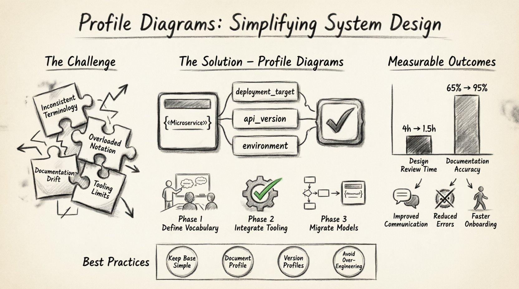
- Inconsistent Terminology: One team referred to a “Database Connection Pool,” while another called it a “Resource Manager.” This led to confusion during code reviews and integration testing.
- Overloaded Notation: Standard UML class diagrams were being used to describe infrastructure components, such as queues and message brokers, which were not natively supported by the base notation.
- Documentation Drift: As the system evolved, diagrams were rarely updated. The visual representation no longer matched the deployed reality.
- Tooling Limitations: Generic modeling tools did not support the specific constraints required for our security and compliance layers.
Standard UML provides a robust foundation, but it is not always sufficient for specialized domains. Without a mechanism to extend the language, teams were forced to rely on informal conventions, comments, or external documents that quickly became obsolete. We needed a formal way to customize the notation to fit our specific needs without breaking the underlying model integrity.
What is a Profile Diagram? The Technical Foundation 🛠️
A profile diagram is a specialized UML diagram used to extend the capabilities of a modeling language. It allows architects to define new constructs based on existing metaclasses. This process involves creating stereotypes, tagged values, and constraints that apply to specific elements within the system.
Unlike a standard class diagram, which describes the structure of data, a profile diagram describes the structure of the model itself. It acts as a vocabulary layer. When this profile is applied to a system model, it enriches the elements with domain-specific meaning.
Key Components of a Profile
To understand how this simplifies design, one must understand the building blocks:
- Stereotypes: These are new types of elements derived from existing metaclasses. For example, extending the
Classmetaclass to create a<<Microservice>>stereotype. This allows us to visually distinguish services from standard data classes. - Tagged Values: These are additional properties attached to elements. A microservice might have a tagged value for
deployment_targetorapi_version, which standard classes do not natively possess. - Constraints: Rules that restrict how elements can be used. For instance, a constraint ensuring that a
<<Database>> element only connects to specific service types.
The Case Study: Implementation Strategy 📈
Our team embarked on a project to redesign the core transaction processing engine. The goal was to reduce ambiguity in the design phase and improve the accuracy of the generated documentation. We decided to adopt a profile-based approach.
Phase 1: Defining the Domain Vocabulary
The first step was not drawing diagrams, but defining the language. We held workshops with domain experts to identify recurring patterns and concepts that lacked standard representation.
Examples of concepts we profiled included:
- Security Context: We defined a stereotype for authentication layers that could be applied to any interaction point.
- Data Residency: Tagged values were created to specify where data could physically reside, complying with regional regulations.
- Service Contract: A constraint was added to ensure that all public interfaces adhered to a specific versioning schema.
This phase required careful planning. We created a namespace for our profile to avoid conflicts with future standard updates. This ensured that our extensions remained stable even if the base modeling language evolved.
Phase 2: Integrating into the Modeling Environment
Once the profile definitions were finalized, we integrated them into our modeling tool. This involved registering the profile package and making it available to all users in the environment. The tooling allowed us to load the profile and apply it to existing models.
The integration process included:
- Validation Rules: We configured the environment to validate that all elements using our new stereotypes followed the defined constraints.
- Template Creation: We created reusable templates for common patterns, such as the standard API gateway structure, to speed up design.
- Documentation Generation: We configured the tool to generate documentation directly from the profiled elements, ensuring that tagged values were included in the output.
Phase 3: Migration of Existing Models
Migrating existing diagrams was the most labor-intensive part of the project. We could not simply overwrite the old models. Instead, we used a phased approach.
For each major subsystem:
- We created a new diagram using the profile.
- We mapped the old elements to the new stereotypes.
- We verified the tagged values against the source code.
- We retired the old diagrams once the new ones were validated.
This migration strategy minimized risk. If an error occurred in the mapping, it could be isolated to a specific subsystem without affecting the entire architecture.
Benefits Realized: Measurable Outcomes 📊
After six months of operation with the profile-based design process, we conducted a review of the impact. The results were significant and quantifiable.
Improved Communication
The most immediate benefit was semantic clarity. When a developer saw the <<AsyncQueue>> stereotype, they immediately understood the behavior without needing to read additional documentation. The visual notation carried the meaning.
Reduced Error Rates
By enforcing constraints through the profile, we caught architectural violations earlier in the design phase. For example, the constraint preventing direct database connections from external services eliminated a common security vulnerability before code was written.
Faster Onboarding
New team members could understand the system faster. The standardized profiles acted as a training manual. Instead of learning a new custom notation from scratch, they learned the profile, which defined the specific system vocabulary.
Table: Before vs. After Implementation
| Metric | Before Profile Implementation | After Profile Implementation |
|---|---|---|
| Design Review Time | 4 hours per subsystem | 1.5 hours per subsystem |
| Documentation Accuracy | 65% (estimated) | 95% (verified via code scan) |
| Terminology Conflicts | High (multiple terms per concept) | Low (single source of truth) |
| Tooling Support | Generic only | Domain-specific extensions |
Best Practices for Profile Design 🎯
Creating a profile is not a trivial task. It requires discipline to ensure it remains maintainable and useful over time. Based on our experience, we recommend the following practices.
1. Keep the Base Simple
Do not create a profile that overrides the base language. Instead, extend it. If a standard UML class can represent a concept, use it. Only create a stereotype if there is a distinct semantic difference that needs to be communicated.
2. Document the Profile Itself
A profile is software in its own right. It needs a specification. We created a document detailing every stereotype, tagged value, and constraint. This document served as the reference for all future development.
3. Version Your Profiles
Just like the system code, profiles evolve. We implemented a versioning scheme for our profiles. When a new version was released, we updated the models incrementally. This prevented breaking changes from cascading through the entire architecture.
4. Avoid Over-Engineering
It is easy to create too many stereotypes. We found that if a concept does not appear in at least three different diagrams, it might be too specific to warrant a stereotype. We focused on high-frequency patterns.
Common Pitfalls and How to Avoid Them ⚠️
Even with a solid plan, challenges arose. Identifying these pitfalls early can save significant time.
Pitfall: Tool Dependency
If the profile is tightly coupled to a specific tool, moving to a new environment becomes difficult. We mitigated this by keeping the profile definitions in a neutral format that could be imported into various modeling environments.
Pitfall: Ignoring Tooling Feedback
We initially ignored validation warnings from the tooling, assuming they were false positives. This led to models that looked correct but failed code generation. We learned to treat validation errors as critical blockers.
Pitfall: Lack of Governance
Without a governance process, team members created their own ad-hoc extensions. This led to a fragmented profile. We established a core team responsible for approving any changes to the profile definition.
Future Considerations and Evolution 🔄
System design is not static. As technology evolves, so must our modeling approaches. We are currently exploring how to integrate these profiles with automated testing frameworks. The goal is to generate test cases directly from the tagged values within the profile.
Additionally, we are investigating the use of profile diagrams for non-functional requirements. Currently, profiles focus on structure and behavior. Extending them to capture performance metrics or security policies could further unify the design and implementation phases.
The flexibility of the profile mechanism allows us to adapt without rewriting the entire system. If a new infrastructure pattern emerges, we can define a new stereotype and apply it immediately. This agility is crucial in modern software development.
Final Thoughts on Architectural Clarity 🌟
The journey to simplify our system design process was not about finding a magic tool or a single piece of software. It was about standardizing the language we use to communicate complex ideas. Profile diagrams provided the mechanism to do this within a familiar framework.
By extending the base modeling language to match our domain vocabulary, we reduced cognitive load. Developers spent less time deciphering diagrams and more time writing code. Architects spent less time reconciling conflicting models and more time planning for scalability.
The adoption of profile diagrams demonstrated that structured extensibility is a viable path forward for enterprise architecture. It balances the need for standardization with the necessity of domain specificity. As we continue to evolve, this approach will remain the foundation of our design strategy, ensuring that our systems remain clear, consistent, and maintainable.