
In the landscape of software architecture and system design, precision is paramount. Standard modeling languages provide a foundation, but they often lack the specificity required for unique domain requirements. This is where the Profile Diagram becomes an essential tool for technical teams. This comprehensive guide explores the mechanics, purpose, and implementation of Profile Diagrams within the Unified Modeling Language (UML) ecosystem.
🧩 Understanding the Core Concept
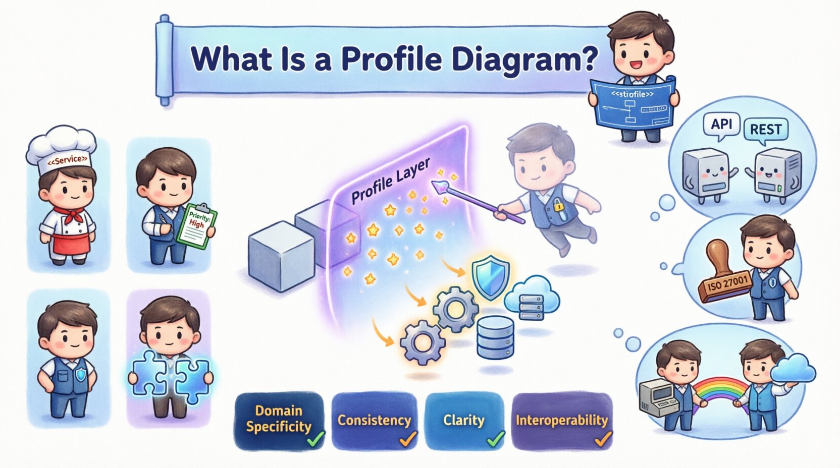
A Profile Diagram is a specialized type of UML diagram designed to extend the vocabulary of the modeling language itself. Think of it as a way to customize the language to fit a specific project or industry domain without altering the core standard. It allows architects and developers to introduce new concepts, known as stereotypes, that align with business terminology or technical constraints.
Standard UML diagrams cover general structures like classes, use cases, and interactions. However, not every system fits neatly into these generic boxes. A Profile Diagram bridges the gap by defining how existing UML elements should be interpreted within a specific context.
- Primary Function: To extend UML metamodels.
- Target Audience: System architects, technical leads, and modelers.
- Output: A defined set of extensions applied to models.
🏗️ The Anatomy of a Profile
To understand how a Profile Diagram functions, one must dissect its internal components. It is not merely a drawing; it is a structured definition of metadata. The following table breaks down the essential building blocks.
| Component | Definition | Example Usage |
|---|---|---|
| Stereotype | A tag that extends the metaclass to a new category. | Defining a class as "Service" or "Controller". |
| Tagged Value | A property attached to an element to store specific data. | Adding a "Priority" tag to a requirement. |
| Constraint | A rule or restriction that limits element behavior. | Ensuring a database table cannot be deleted. |
| Relationship | Links between profile elements and base elements. | Connecting a stereotype to a standard Class. |
🔍 Why Use Profile Diagrams?
Technical teams often face the challenge of communication. Stakeholders speak in business terms, while developers speak in code terms. A Profile Diagram standardizes this translation. It ensures that when a modeler sees a specific icon or label, they understand the exact implication.
Key Benefits
- Domain Specificity: Adapt the model to the industry (e.g., healthcare, finance, embedded systems).
- Consistency: Enforce naming conventions and structural rules across large codebases.
- Documentation Clarity: Make diagrams readable for non-technical stakeholders by using familiar terms.
- Tool Interoperability: Facilitate the exchange of models between different platforms by defining a common extension layer.
📝 Creating a Profile: Step-by-Step Logic
Developing a profile involves a logical process of definition, association, and application. This process does not rely on specific tools but follows the structural rules of the modeling standard.
1. Identify the Need
Before drawing, determine why the standard UML is insufficient. Is there a recurring pattern that needs a label? Are there specific properties that every component must have?
2. Define the Metaclass
Select the existing UML element you wish to extend. Common choices include:
- Class: For defining software components.
- Component: For architectural blocks.
- Use Case: For functional requirements.
- Package: For organizing structure.
3. Create Stereotypes
Extend the chosen metaclass by creating stereotypes. These are usually displayed with guillemets, such as <<API>> or <<Database>>. Each stereotype represents a distinct role within your system.
4. Add Tagged Values
Attach properties to your stereotypes. If you define a "Database" stereotype, you might add tags for:
- Engine: (e.g., PostgreSQL, MySQL)
- Schema: (e.g., Public, Private)
- Version: (e.g., v1.0)
5. Apply Constraints
Ensure the model adheres to rules. For instance, a stereotype might specify that a certain class cannot have a direct relationship with another without passing through a controller layer.
🔄 Profile vs. Standard UML
It is crucial to distinguish between standard UML diagrams and those utilizing profiles. The former uses pre-defined semantics, while the latter introduces custom semantics.
| Feature | Standard UML | Profile Diagram |
|---|---|---|
| Scope | General purpose | Domain specific |
| Semantics | Fixed definition | Custom definition |
| Flexibility | Lower (rigid structure) | Higher (adaptable) |
| Adoption | Universal | Team or Project specific |
🚀 Practical Use Cases
Profile diagrams are not theoretical exercises; they solve real engineering problems. Below are common scenarios where they add value.
1. Microservices Architecture
In a distributed system, distinguishing between a synchronous API and an asynchronous event handler is vital. A profile can define stereotypes like <<SyncService>> and <<AsyncQueue>>. This makes the architectural intent visible at a glance.
2. Security Compliance
For systems handling sensitive data, a profile can enforce security tags. Elements can be tagged with <<PII>> (Personally Identifiable Information) or <<Encrypted>>. This ensures that security requirements are modeled alongside functional requirements.
3. Legacy Integration
When integrating older systems, a profile can map legacy concepts to modern standards. For example, mapping a mainframe "File" to a modern "Object Store" stereotype allows teams to visualize the migration path clearly.
⚠️ Common Pitfalls and Best Practices
While powerful, profile diagrams can introduce complexity if mismanaged. Adhering to best practices ensures the model remains maintainable.
Pitfalls to Avoid
- Over-Extension: Do not create a stereotype for every single variation. Keep the profile lean.
- Ambiguity: Ensure every stereotype has a clear, documented definition.
- Inconsistency: Do not mix standard UML notation with profile notation randomly. Apply the profile consistently across the entire model.
- Dependency Hell: Avoid creating deep dependency chains between profiles. Keep profiles modular.
Best Practices
- Documentation: Maintain a separate document explaining the profile definitions.
- Versioning: Treat the profile itself as a versioned artifact. Changes to the profile should be tracked.
- Tool Support: Ensure your modeling environment supports the profile definition syntax.
- Review: Include profile definitions in code reviews or architecture review board (ARB) meetings.
📐 Technical Implementation Details
Understanding the technical layer helps in managing the profile lifecycle. Profiles interact with the underlying metamodel.
Metamodel Extension
The metamodel is the blueprint of the modeling language. A profile extends this blueprint. When you define a stereotype, you are essentially adding a new type to the metaclass hierarchy. This allows the modeling tool to recognize the new type and render it appropriately.
Namespace Management
Profiles exist within namespaces. This prevents naming collisions. If two teams define a stereotype named "Service", they must reside in different namespaces to avoid confusion. Proper namespace management is critical for large organizations.
Serialization and Persistence
When saving models, the profile definitions must be included or referenced. If a profile is defined in one model but used in another, the receiving model needs to know the definitions. This is often handled through import mechanisms or shared library files.
🤝 Collaboration and Communication
One of the primary goals of a profile diagram is to improve communication. It acts as a shared vocabulary.
- For Developers: Provides clear hints on implementation patterns.
- For Architects: Ensures high-level design decisions are reflected in the model.
- For QA: Highlights specific constraints and testing requirements via tagged values.
- For DevOps: Identifies infrastructure needs through component stereotypes.
🛠️ Maintenance and Evolution
Profiles are not static. As the system evolves, the profile may need to change. This requires a governance process.
- Proposal: A team member suggests a new stereotype or tag.
- Review: The architecture team evaluates the necessity and impact.
- Update: The profile diagram is modified.
- Communication: The update is notified to all users of the model.
- Migration: Existing models are updated to reflect the new profile.
🔗 Integration with Other Diagrams
A profile diagram is often the foundation for other diagrams. Once a profile is defined, it can be applied to Class Diagrams, Sequence Diagrams, and Deployment Diagrams.
- Class Diagrams: Apply stereotypes to classes to indicate their role (e.g., Repository, Factory).
- Sequence Diagrams: Use tagged values on lifelines to specify protocol or security level.
- Deployment Diagrams: Mark nodes with environment-specific tags (e.g., "Production", "Staging").
🌐 Industry Standards and Interoperability
While profiles are often custom, there are industry-wide profiles that promote interoperability. For example, the Model-Driven Architecture (MDA) initiative defines specific profiles to map platform-independent models to platform-specific implementations.
Adhering to recognized standards where possible reduces the learning curve for new team members and facilitates tool integration. However, do not be afraid to deviate when standard profiles do not meet specific project needs.
📊 Summary of Value
The Profile Diagram is a sophisticated mechanism for enhancing modeling precision. It allows technical teams to tailor the UML language to their unique architectural constraints and business domains. By defining stereotypes, tagged values, and constraints, teams create a shared language that reduces ambiguity and improves documentation quality.
When implemented correctly, it transforms a diagram from a static picture into a rich, information-dense artifact that guides development and maintenance. It is not about adding complexity; it is about adding clarity.
📝 Conclusion
Effective system design requires more than just drawing boxes and arrows. It requires a structured way to communicate intent. Profile diagrams provide this structure. They enable teams to extend standard modeling tools without breaking compatibility or losing the benefits of the underlying standard.
For technical leaders, investing time in defining and maintaining a robust profile is an investment in the longevity and clarity of the system architecture. It ensures that as the team grows and the system scales, the documentation remains a reliable source of truth.